Rotor and Reluctance Machine

a reluctance machine and rotor technology, applied in the direction of dynamo-electric machines, magnetic circuit rotating parts, magnetic circuit shape/form/construction, etc., can solve the problems of inability to meet the precondition, comparatively complicated structure and cost of conventional starting cages, which are composed of conductor bars and short-circuiting rings

Active Publication Date: 2017-08-03
KSB AG
View PDF3 Cites 5 Cited by
  • Summary
  • Abstract
  • Description
  • Claims
  • Application Information

AI Technical Summary

Benefits of technology

[0021]Owing to the rotor geometry according to the invention and the corresponding filling ratio of the individual flux barriers, it is possible to produce an optimum starting cage, but with the mass of the filler material and therefore the mass of the starting cage formed being kept as small as possible. A line-start synchronous reluctance motor can be formed by the rotor, it being possible to operate said line-start synchronous reluctance motor in a fixed grid without problems and also to start said line-start synchronous reluctance motor without a frequency converter owing to the design of the aluminum cage, and said line-start synchronous reluctance motor running until complete synchronization with the grid voltage.

Problems solved by technology

However, the structure and manufacture of conventional starting cages, comprising conductor bars and short-circuiting rings, have been comparatively complicated and expensive to date.
Under certain circumstances, this precondition cannot be met for the flux barriers with the smallest area since said flux barriers do not provide enough filling space for the area specification.

Method used


Image

  • Rotor and Reluctance Machine
  • Rotor and Reluctance Machine
  • Rotor and Reluctance Machine

Examples


Embodiment Construction

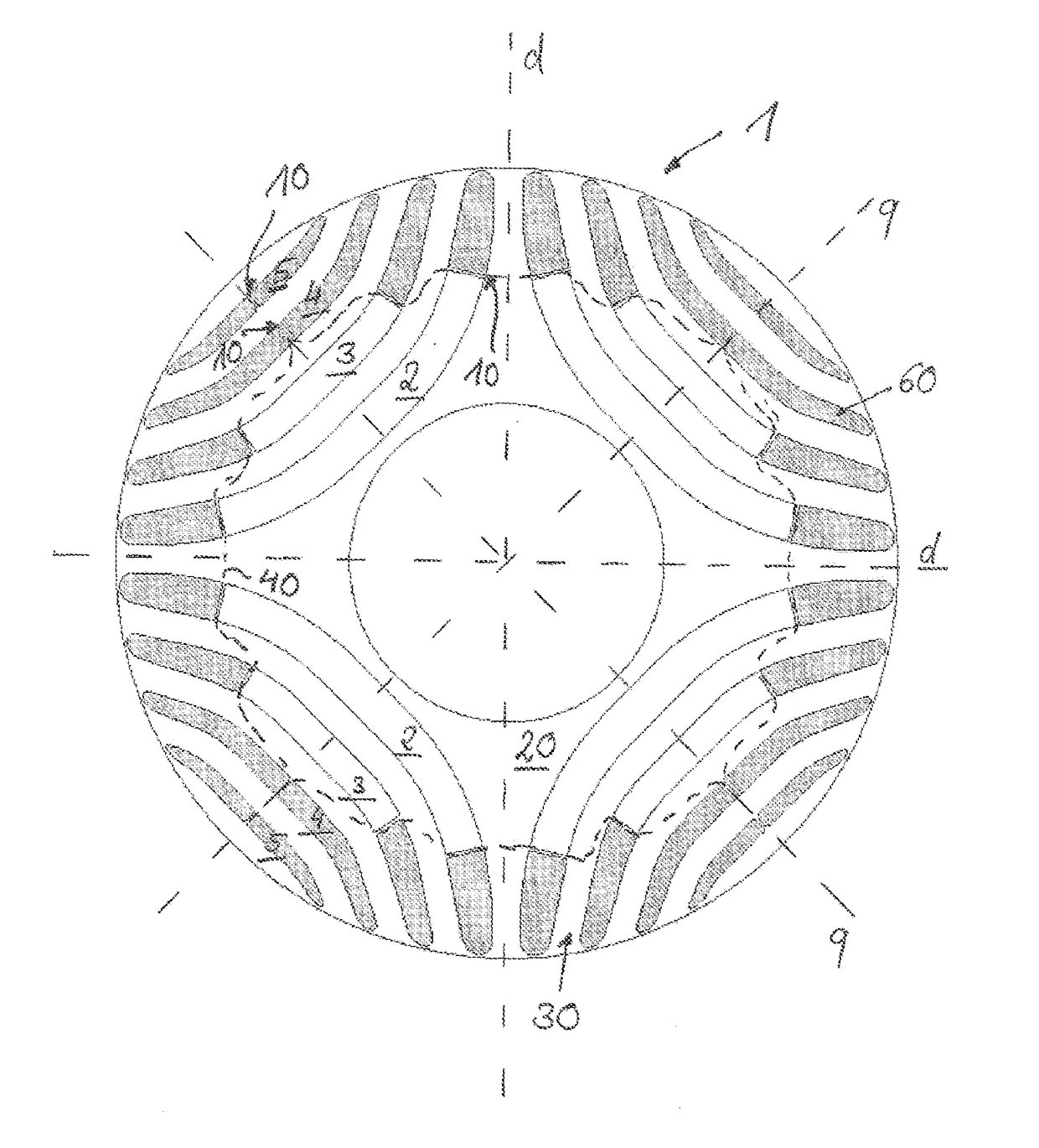
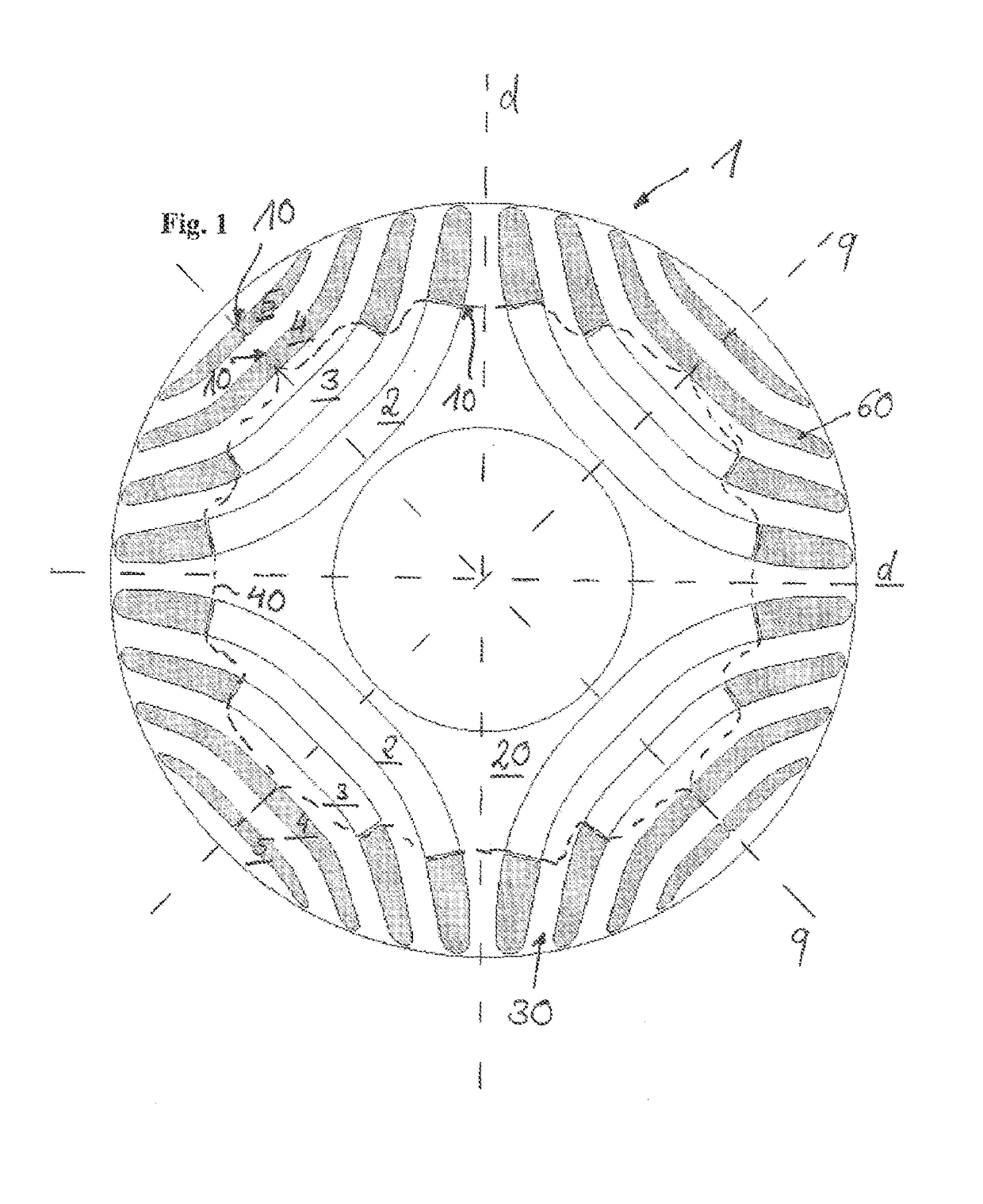
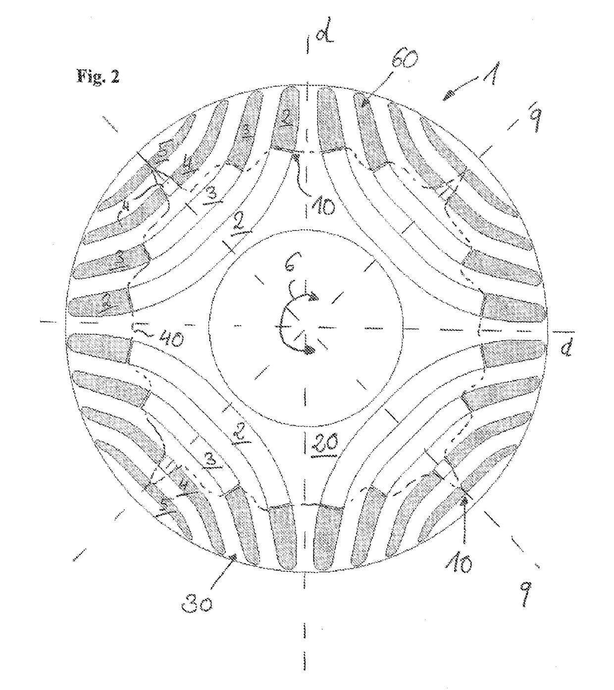
[0029]FIGS. 1 to 3 show plan views of a rotor lamination 1 of different design variants of the rotor according to embodiments of the invention. A large number of laminations 1 of this kind are stacked one on top of the other in an axial direction, that is to say along the rotation axis 6, for the construction of the rotor according to the invention. As an alternative, the rotor can also be designed as a block, the cross section of said block corresponding to the shown illustration of FIGS. 1 to 3.

[0030]In order to simplify the illustration, the stator is not shown. The rotor lamination 1 has a plurality of cutouts 2, 3, 4, 5, which take on the function of flux barriers and the arrangement of which forms a four-pole rotor, the magnetic flux of said rotor being inhibited in the regions with the flux barriers 2, 3, 4, 5. The region with high magnetic conductivity is generally identified as the d-axis, and the region of lower magnetic conductivity is generally identified as the q-axis. ...


PUM


Abstract

A rotor for a reluctance machine is provided. The rotor includes a soft magnetic element which is cylindrical in shape. The soft magnetic element has recesses forming flux barriers. At least part of the recesses are filled with an electrically conducting and magnetically non-conducting filler material such that a starting cage is formed in a peripheral region of the rotor. The ratio of the surface of the filled region of the flux barriers to the surface of the region of the unfilled flux barriers is at least 0.2 for at least one rotor cycle.

Description

[0001]This application is a National Stage of PCT International Application No. PCT / EP2015 / 067904, filed Aug. 4, 2015, which claims priority under 35 U.S.C. §119 from German Patent Application No. 10 2014 215 303.4, filed Aug. 4, 2014, the entire disclosures of which are herein expressly incorporated by reference.BACKGROUND AND SUMMARY OF THE INVENTION[0002]The invention relates to a rotor for a reluctance machine comprising a cylindrical soft-magnetic element, wherein the soft-magnetic element has cutouts for forming magnetic flux barriers and at least some of the cutouts are filled with an electrically conductive and magnetically non-conductive filler material, in order to form a starting cage of the rotor.[0003]Rotors for synchronous reluctance machines are usually equipped with a cylindrical soft-magnetic element which is arranged coaxially on the rotor axis. In order to form at least one pole pair or gap pair, the soft-magnetic element comprises flux-conducting and flux-blockin...

Claims


Application Information

Patent Timeline
Patent Type & Authority Applications(United States)
IPC IPC(8): H02K1/24H02K19/02
CPCH02K1/246H02K2213/03H02K19/02
Inventor JANJIC, BORISSCHAAB, JOCHEN
Owner KSB AG
Why Eureka
Try Eureka