Device for forming a dental prosthesis

a dental prosthesis and device technology, applied in dental prosthesis, medical science, dentistry, etc., can solve the problems of time-consuming and unpleasant patient discomfort, difficult and time-consuming for patients, and the known attachment of structural elements for forming crowns, bridges or prostheses with several teeth,

Inactive Publication Date: 2001-12-25
STRAUMANN HLDG AG +1
View PDF7 Cites 158 Cited by
  • Summary
  • Abstract
  • Description
  • Claims
  • Application Information

AI Technical Summary

Problems solved by technology

This known device has the disadvantage that it is often difficult, time consuming and unpleasant for the patient to first screw the impression cap fast to the support in the patient's mouth and after the impression to unscrew it again.
Since the latch brackets are located outside on the end designated for attachment with the support, the known impression cap is not suited for taking the impression of the shoulder of the support and the support's surroundings.
The known detachable connection of the healing element using screws and the known attachment of structural elements for forming crowns, bridges or prostheses with several teeth and / or a superstructure using screwing means of attachment is likewise often difficult and time consuming.

Method used


Image

  • Device for forming a dental prosthesis
  • Device for forming a dental prosthesis
  • Device for forming a dental prosthesis

Examples


Embodiment Construction

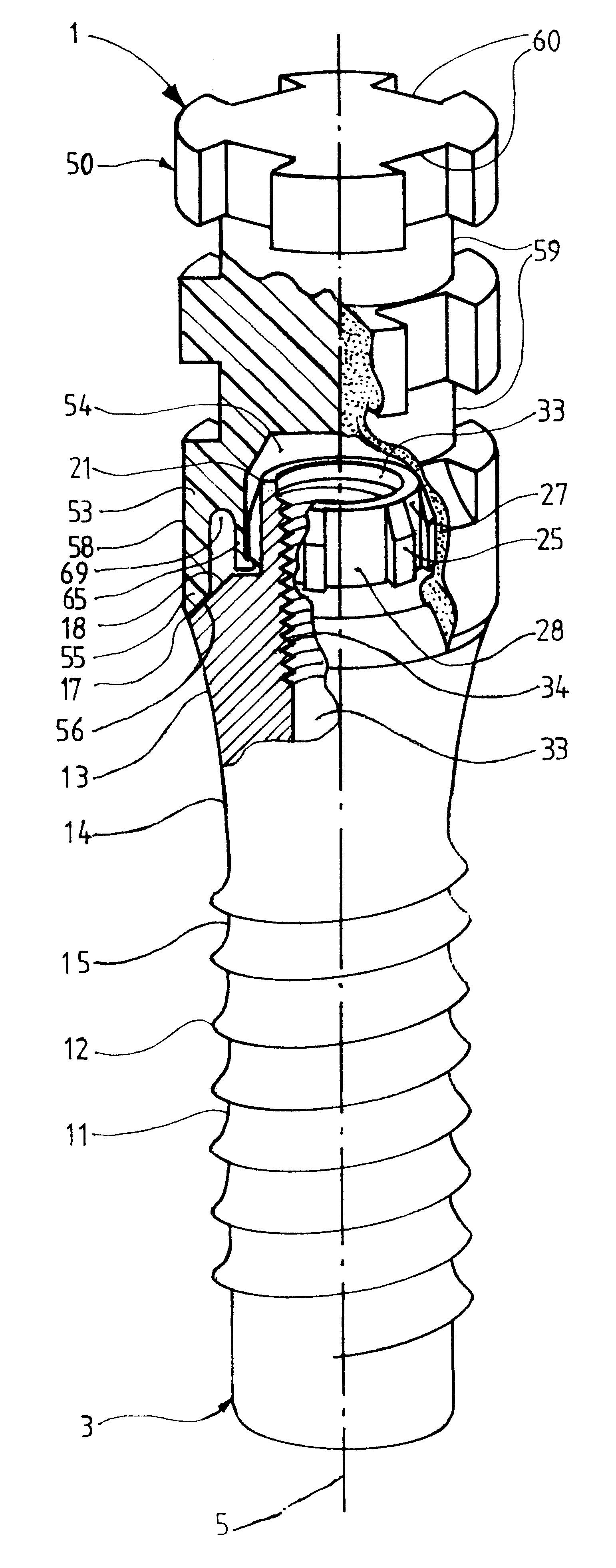
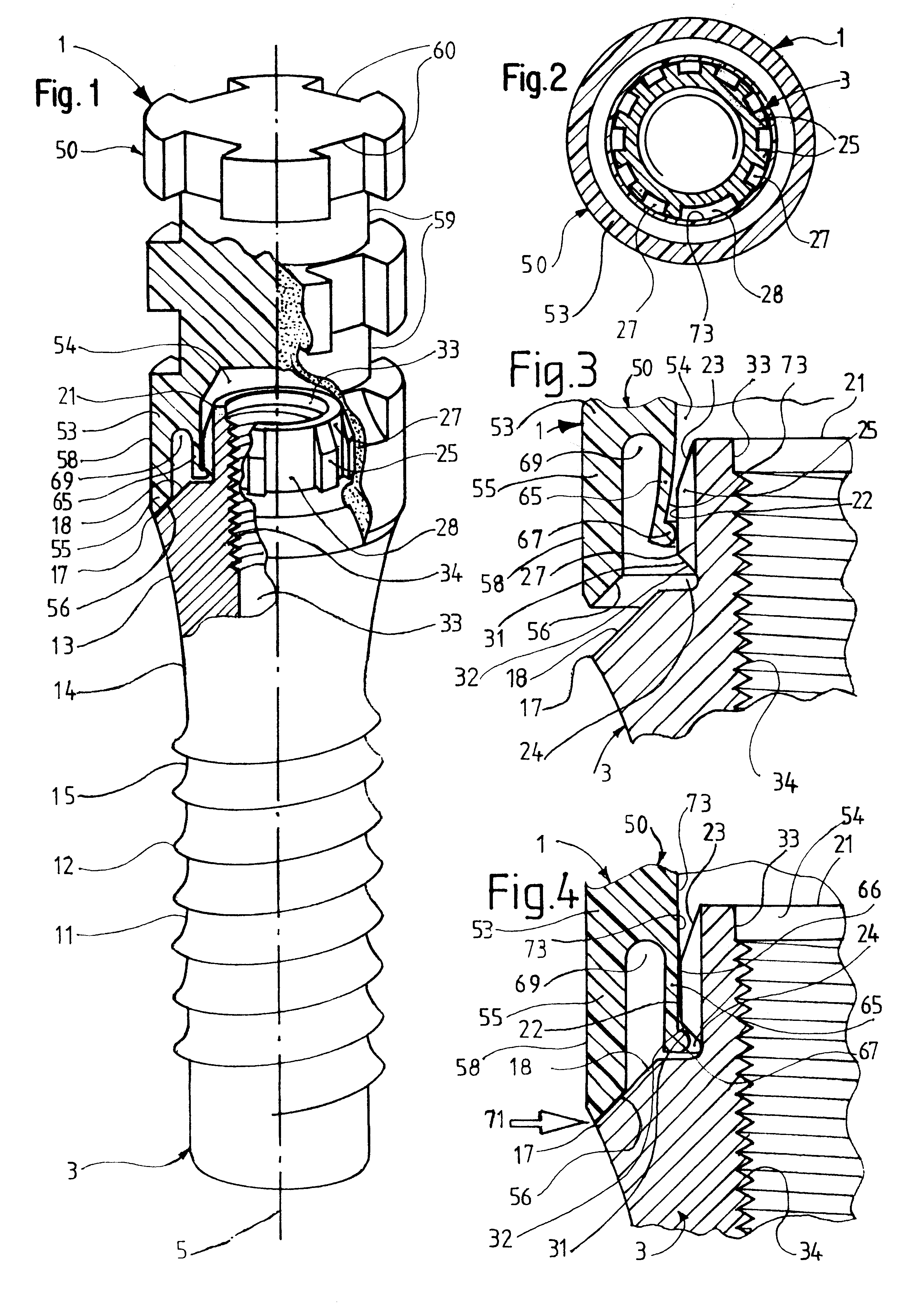
The device 1 seen in the FIGS. 1 through 4 has a support 3 comprising a one-piece implant. The support 3, or the implant, is longish and generally rotationally symmetric to an axis 5. The support 3 has a generally cylindrical section 11 with an outer threading 12 and a section 13 which is trumpet shaped, expanding away from the cylindrical section 11 in an upwards direction. The sections 11, 13 have a casing surface and / or outer surface 14. Together, the cylindrical section 11 and the lower end of the trumpet-shaped section 13 form the anchoring part 15 of the support 3. This, on the upper end of the trumpet-shaped section 13, has a shoulder 17 with an annular, conical shoulder surface 18, which is inclined from the anchoring part 13 towards the axis 5, forms an angle with it of 40.degree. to 50.degree., for example 45.degree., and has a fully circular outer edge.

The support 3 has a narrow, annular, flat surface adjoining the upper inner edge of the conical shoulder surface 18 and h...


PUM


Abstract

A device for forming a dental prosthesis includes a support and an element which can be attached thereto, such as an impression element. The support has an anchoring part for anchoring in a bone or a master model, a shoulder with an annular shoulder surface, and a head. The impression element has an elastically deformable fixing agent. When the device is assembled, the fixing agent jams and/or latches with the support, either externally on the support, on the side of the shoulder facing the anchoring part, or in an axial hole of the support. The element can be quickly detachably connected to the support by placing it on top of the support, and can be quickly separated from the support by moving the support away. When the device is assembled, the support and the element can lay on top of each other with annular surfaces. The annular surfaces have fully circular outer edges which are visible from the outside in an approximately radial viewing direction.

Description

The invention relates to a device for forming a dental prosthesis having a support and having an element which can be detachably connected using fixing means, where the support has an anchoring part designed to anchor in a bone and / or master model, a head designed to protrude from the bone or master model, and a shoulder present between this and the anchoring part. The dental prosthesis can involve a single false tooth, a bridge or a prosthesis forming several teeth. For example, the support can comprise a one-piece body or an implant and a secondary part, originally separate, which is fixed to the implant. The element which can be fixed on the support can, for example, comprise an impression element. This is also often called an impression cap or molding cap and, with the aid of an impression tray and impression material held by this and plastically shapeable for at least a certain period, is used to make an impression or a mold of the soft tissue surrounding the, or at least one, ...

Claims


Application Information

Patent Timeline
Patent Type & Authority Patents(United States)
IPC IPC(8): A61C13/225A61C8/00A61C13/265
CPCA61C8/0001A61C8/005A61C8/0066A61C8/0069A61C8/008A61C13/2656
Inventor SUTTER, FRANZ
Owner STRAUMANN HLDG AG
Why Eureka
Try Eureka