Method of allocating work in capacity planning

a technology of capacity planning and allocation of work, applied in the field of capacity planning, can solve the problems of large capital investment and depreciation burden of tool set, less reliable tool, and older, and achieve the effects of reducing the number of tools, and reducing the number of resources

Inactive Publication Date: 2002-01-22
IBM CORP
View PDF8 Cites 49 Cited by
  • Summary
  • Abstract
  • Description
  • Claims
  • Application Information

AI Technical Summary

Problems solved by technology

This tool set may represent a large capital investment ($1B for semiconductor fabrication) and depreciation burden.
The second best may be an older, slower, less reliable tool.
However, in the more complex manufacturing environments in which different tools can perform the same or similar sets of operations, generally at different rates, these decisions become much more difficult because of the different ways in which work c

Method used


Image

  • Method of allocating work in capacity planning
  • Method of allocating work in capacity planning
  • Method of allocating work in capacity planning

Examples


example a

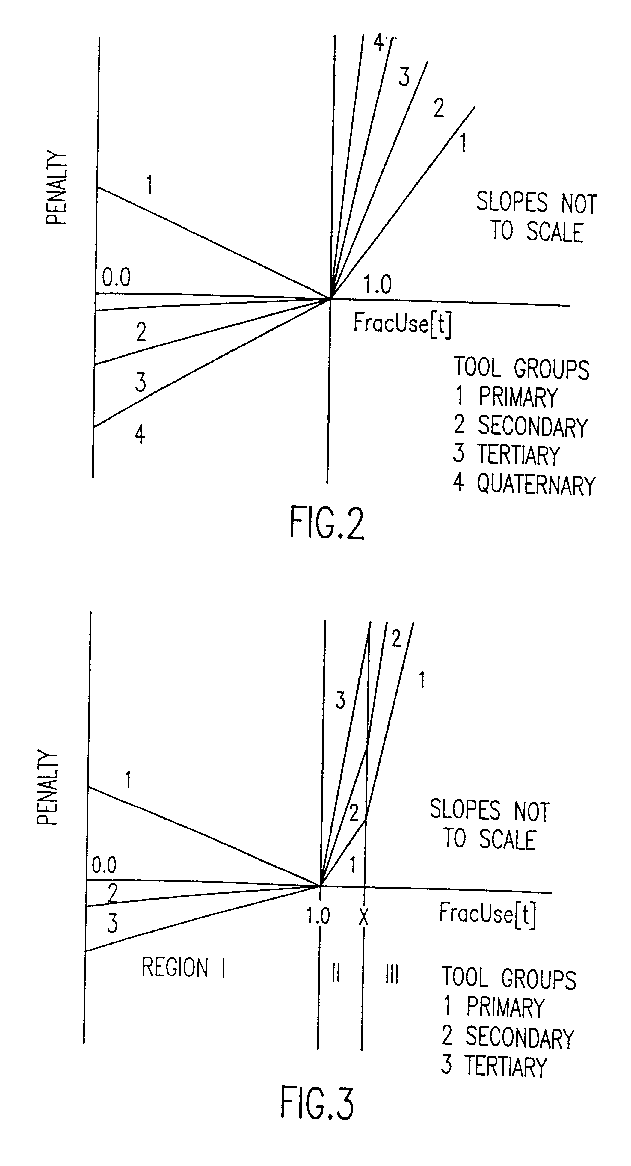
demonstrates the case where additional work can be accommodated on the secondary and tertiary tool groups. The primary tool group, nominally at 100% of capacity, is sitting at the beginning of region II with FracUse=1.000. In example B, the primary tool group has been forced to move up to the upper end of region II (FracUse=1.001) because the lower ranked tool groups can not take further work. The primary tool group is gating. Example C illustrates the case last described in the paragraph above; i.e., the primary tool group not gating, but the secondary tool group is gating. Case D is described below.

For the case of a non-primary tool group, it is not sufficient that it merely exhibit a FracUse value of 1.001 to qualify as a gating tool group and thus one which should have its number increased. The primary may also have a FracUse of 1.001 indicating the entire cascade set is gating. Additional work could be accommodated on either tool group. In such a case, one would ordinarily want...


PUM


Abstract

A computer implemented method provides accurate capacity planning for manufacturing environments comprising parallel, unrelated tools that can process the same operations at different rates and with preferences for the sequence in which those tools are selected to accommodate the workload. The method reliably determines precisely what are the gating tools among sets of parallel, unrelated tools in a complex manufacturing environment in which different tools can perform the same or similar sets of operations, generally at different rates. The primary, secondary, etc. tool groups in each cascade set are explicitly kept track of in order to enable the correct penalty function to be associated, in one implementation with the appropriate tool group, and in another implementation with the tool allocation variables. The end user may also interact with the input data through a Menu Program or through a Graphical User Interface (GUI) and modify the data for "what-if" analyses.

Description

1. Field of the InventionThe present invention generally relates to a method for allocating work in capacity planning and, more particularly, to a method for accurate capacity planning which deals with parallel, unrelated tools that can process the same operations at different rates and with the preferences for the sequence in which those tools are selected to accommodate the workload.2. Background DescriptionThe capacity of a manufacturing line is characterized by the tool set that occupies the line. This tool set may represent a large capital investment ($1B for semiconductor fabrication) and depreciation burden. It typically consists of multiple generations of tools giving rise to a mix of different equipment with different yields, availabilities and speeds for completing particular operations. Also, engineers typically have an understanding of which tools are best suited to perform a particular operation, which tools are next best, and so on. The best tool may be the fastest or ...

Claims


Application Information

Patent Timeline
IPC IPC(8): G06Q10/00
CPCG06Q10/06
Inventor BERMON, STUARTFEIGIN, GERALD E.
Owner IBM CORP
Why Eureka
Try Eureka