Auxiliary eyewear with laterally distant magnets on lens retaining mechanisms

a technology of magnets and lens retaining mechanisms, which is applied in the field of auxiliary frames with lenses, can solve the problems of obstructing the wearer's vision, scratching the lenses of the primary frame, and scratches on the lenses and the primary frame, and achieves the effects of convenient, firmly and elegantly attaching the auxiliary frame, strong support and easy manufacturing

Inactive Publication Date: 2002-03-05
HUANG DAVID
View PDF15 Cites 35 Cited by
  • Summary
  • Abstract
  • Description
  • Claims
  • Application Information

AI Technical Summary

Benefits of technology

The present invention provides apparatus to easily, firmly and elegantly attach auxiliary frames to primary frames, based on magnets at the lens retaining mechanisms of the auxiliary eyewear. The invention has numerous advantages. For example, it creates a very strong support for attaching auxiliary fr

Problems solved by technology

Not only do such clips obstruct the wearer's vision, they may scratch the lenses of the primary frames.
However, these small clips still create scratches on the lenses and the primary frames; and attaching these auxiliary frames with small clips requires some maneuvering with two hands, and it would not be easy to do so, for example, if one is driving.
Also, to detach such an auxiliary frame from its primary frame, one typically have to push down at its bridge and warp the frames outward on both sides of the lenses.
This is not an easy task especially because the magnets are typically very small for stylistic reasons.
The further away the pair of magnets are on a frame, the more difficult it is to align them in both locations and orientations to magnets on another frame.
Two magnets may not even be able to couple together if they have different orientations.
Misalignment in

Method used


Image

  • Auxiliary eyewear with laterally distant magnets on lens retaining mechanisms
  • Auxiliary eyewear with laterally distant magnets on lens retaining mechanisms
  • Auxiliary eyewear with laterally distant magnets on lens retaining mechanisms

Examples


Embodiment Construction

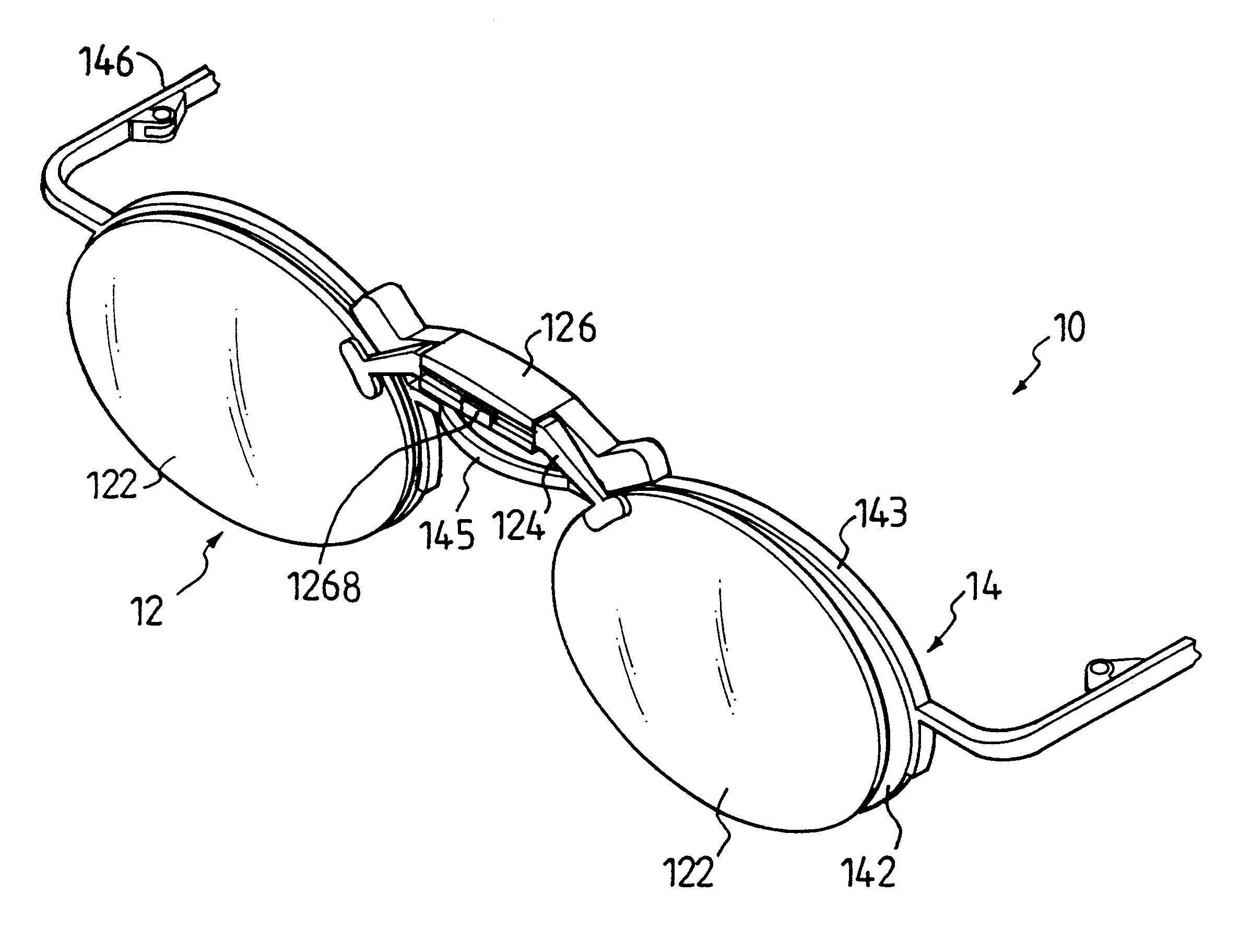
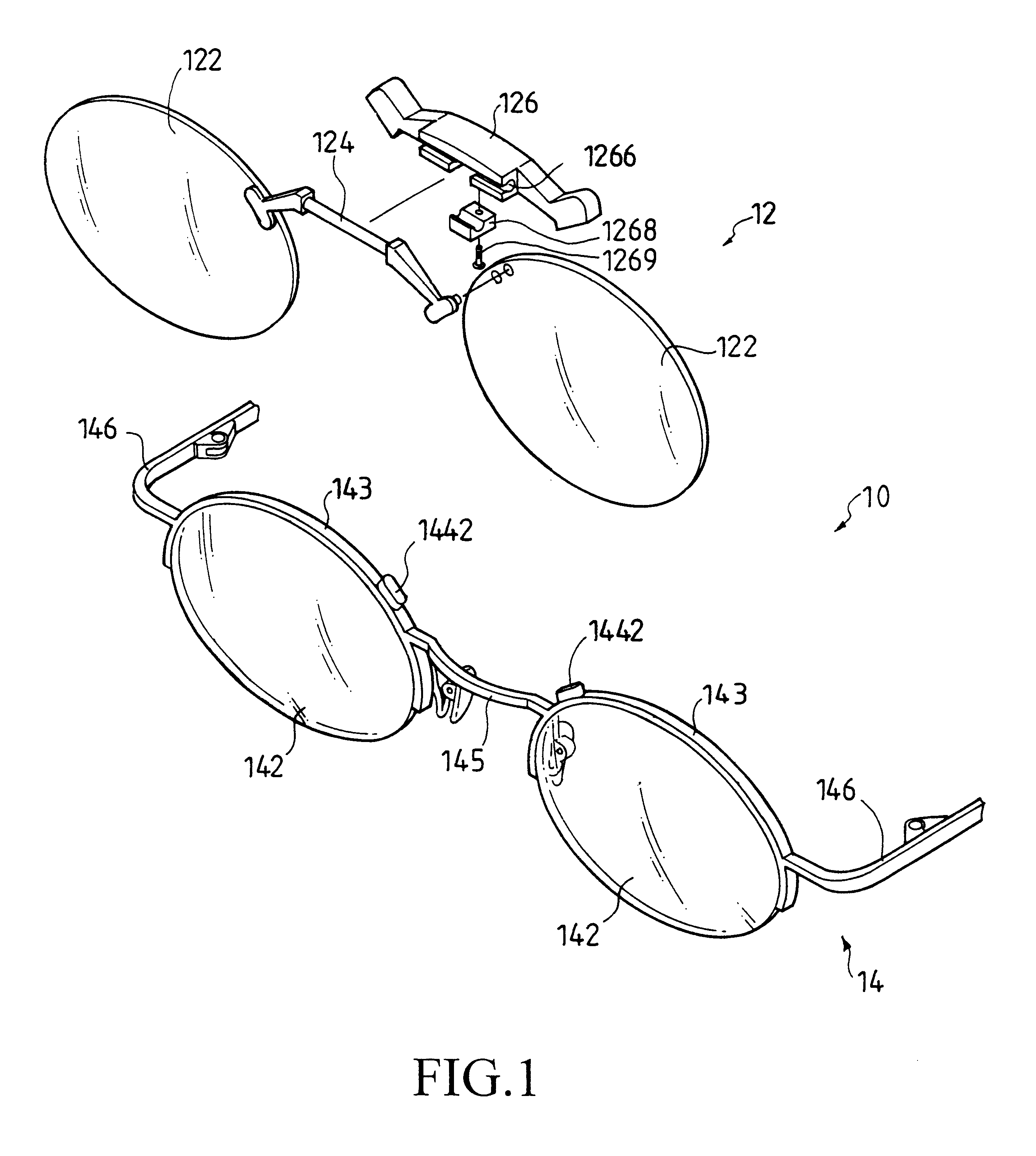
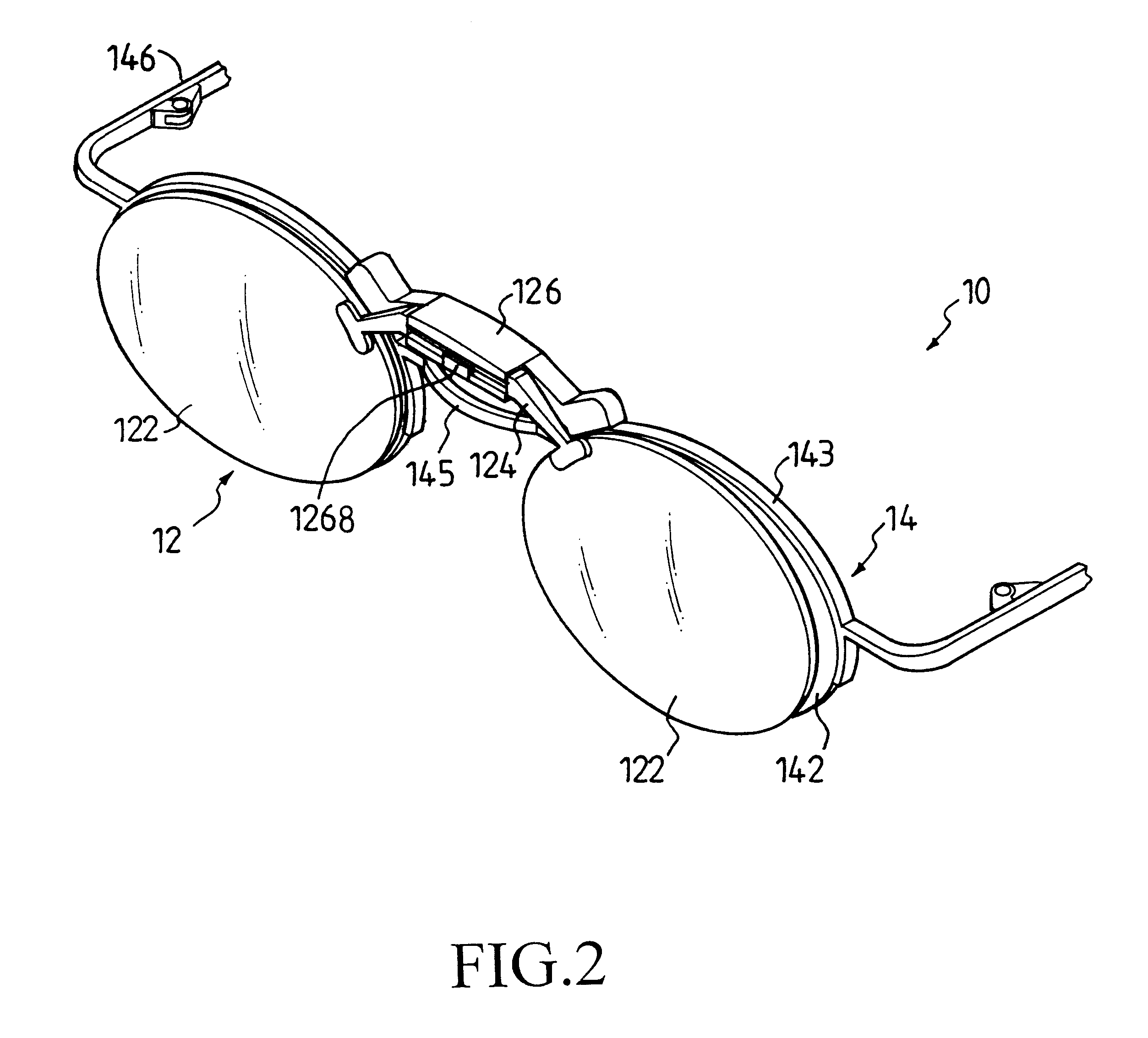
FIG. 1 shows a perspective, exploded view of eyewear 10 of this invention. The eyewear 10 includes an auxiliary frame 12 and a primary frame 14.

The auxiliary frame 12 includes two auxiliary lenses 122; an auxiliary lens retaining mechanism 124 for retaining the auxiliary lenses 122 in a laterally opposed relation; and an attachment mechanism 126 joined to the auxiliary lens retaining mechanism 124 and including two magnets 1262 (FIG. 3) respectively at laterally opposing positions (e.g. ends) thereof.

In this embodiment, the auxiliary lenses 122 are retained together by the auxiliary lens retaining mechanism 124. The auxiliary lenses 122 may also be retained within a pair of closed frames or partial wired frames that are connected by a bridge for stylish purposes.

The primary frame 14 includes two primary lenses 142 forming a lens plane; two primary lens retaining mechanisms 143 for retaining the primary lenses 144; a nose bridge 145 connecting the primary lens retaining mechanisms 14...


PUM


Abstract

Disclosed is an eyewear comprising: an auxiliary frame including: two auxiliary lenses; an auxiliary lens retaining mechanism for retaining the auxiliary lenses in opposed relation; and an attachment mechanism joined to the auxiliary lens retaining mechanism and having two auxiliary magnets at opposing ends thereof; and a primary frame including: two primary lenses forming a lens plane; two primary lens retaining mechanisms for retaining the primary lenses; a nose bridge connecting the primary lens retaining mechanisms in opposed relation; two temples hingedly extending from outer ends of the primary lens retaining mechanism in a direction substantially orthogonal to the lens plane; and two laterally distant, primary magnets each affixed to each of the primary lens retaining mechanism at locations allowing magnetic coupling to the auxiliary magnets. In a further embodiment, the auxiliary lens retaining mechanism of the auxiliary frame is frictionally, pivotally joined to the attachment mechanism to allow flipping up the auxiliary frame when not in use.

Description

This invention is related to an eyewear, and more particularly to a primary and an auxiliary eyewear each having magnets at lens retaining mechanisms thereof for attachment.BACKGROUND OF INVENTIONAuxiliary frames with lenses have been used for decades to augment deficiencies in primary frames. For example, the auxiliary frames may be for magnifying purposes, or may transform the primary frames into sunglasses.For decades, people around the world have been creating numerous ingenious methods to attach the auxiliary frames onto the primary frames. In one line of approaches, the auxiliary frames are clipped onto the lenses of the primary frames. Not only do such clips obstruct the wearer's vision, they may scratch the lenses of the primary frames. To alleviate the defect of view obstruction, there are designs using small clips at the edges of the frames. However, these small clips still create scratches on the lenses and the primary frames; and attaching these auxiliary frames with sma...

Claims


Application Information

Patent Timeline
IPC IPC(8): G02C9/00
CPCG02C9/00G02C2200/02
Inventor HUANG, DAVID
Owner HUANG DAVID
Why Eureka
Try Eureka