
Eyewear frame with auxiliary frame having distantly arranged magnets

a technology of auxiliary frames and magnets, which is applied in the direction of spectacles/goggles, instruments, spectacles/goggles, etc., can solve the problems of obstructing the wearer's vision, scratching the lenses of the main frame, and scratches on the lenses and the main frame, etc., to achieve easy, firmly and elegantly attach the auxiliary frame, and strong support

Inactive Publication Date: 2003-10-28
HUANG DAVID
View PDF21 Cites 18 Cited by
  • Summary
  • Abstract
  • Description
  • Claims
  • Application Information

AI Technical Summary

Benefits of technology

This solution provides a strong, stable, and aesthetically pleasing attachment that can be easily managed with one hand, enhancing usability and design simplicity while allowing the auxiliary frames to be flipped up when not needed.

Problems solved by technology

Not only do such clips obstruct the wearer's vision, they may scratch the lenses of the main frames.
However, these small clips still create scratches on the lenses and the main frames; and attaching these auxiliary frames with small clips requires some maneuvering with two hands, and it would not be easy to do so, for example, if one is driving.
Also, to detach such an auxiliary frame from its main frame, one typically have to push down at its bridge and warp the frames outward on both sides of the lenses.
This is not an easy task especially because the magnets are typically very small for stylistic reasons.
The further away the pair of magnets are on a frame, the more difficult it is to align them in both locations and orientations to magnets on another frame.
Two magnets may not even be able to couple together if they have different orientations.
Misalignment in locations or orientations not only adversely affects the coupling power of the auxiliary frame to the main frame, but also creates an unpleasant outward appearance for the wearer, especially when the auxiliary frame is tilted relative to the main frame.
Another defect with providing the magnets on the temples is that, means cannot be provided to allow the auxiliary frames to flip up, such that the user must remove the auxiliary frames when one does not intend to use the auxiliary frames.
There is a higher probability that the user will lose the auxiliary frames by removing the auxiliary frames from the main frames.
However, the attachment mechanisms provided on the nose bridges along result in a weaker structure and unsteady attachment between the main and auxiliary frames than the attachment mechanisms provided on at least two distant locations of the eyewear.

Method used


Image

  • Eyewear frame with auxiliary frame having distantly arranged magnets
  • Eyewear frame with auxiliary frame having distantly arranged magnets
  • Eyewear frame with auxiliary frame having distantly arranged magnets

Examples


Embodiment Construction

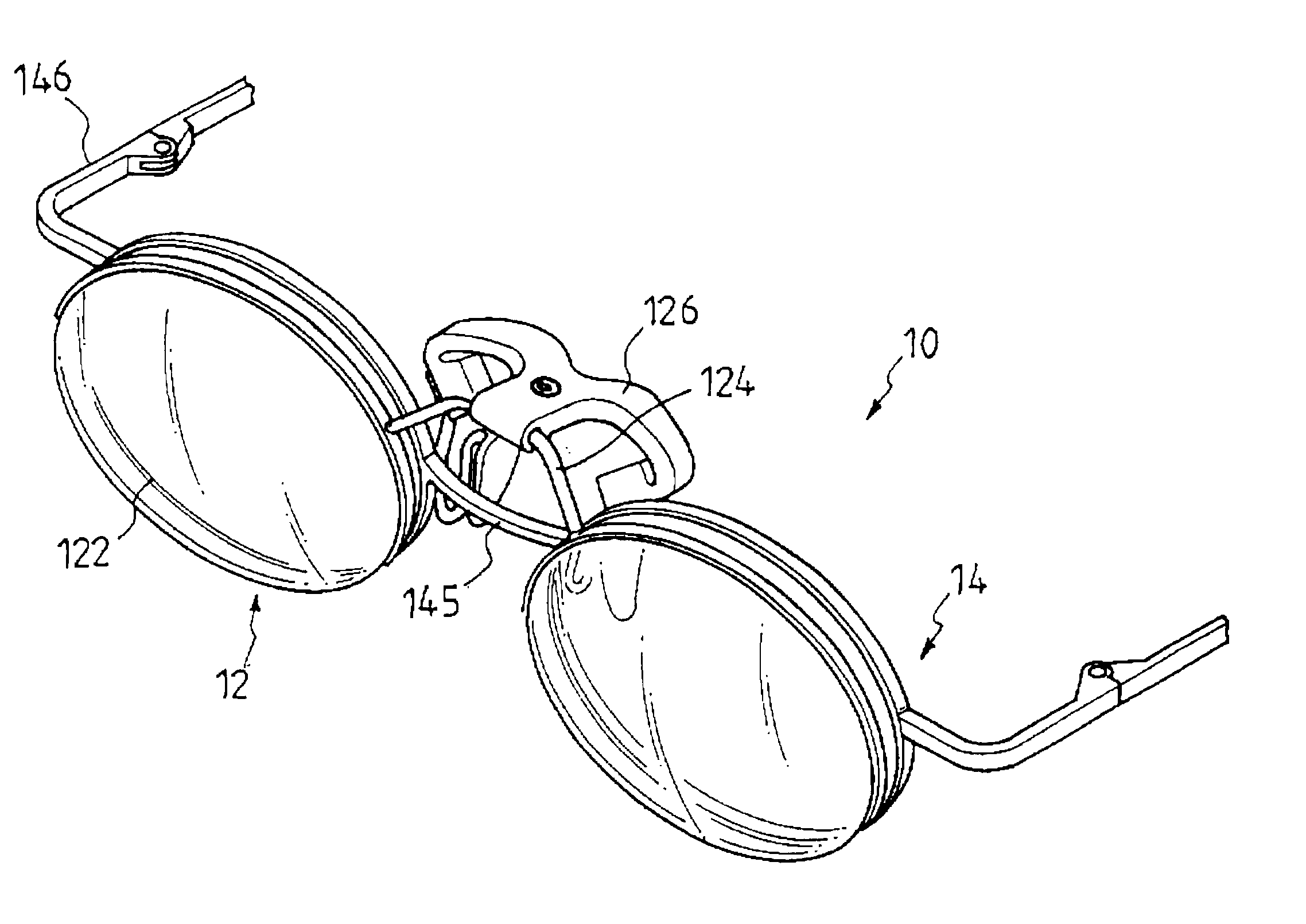
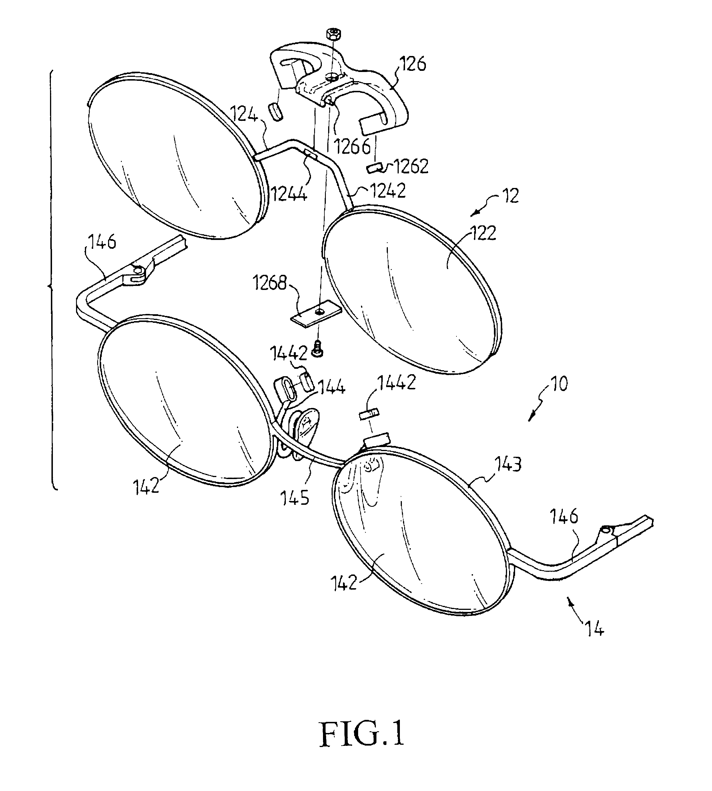
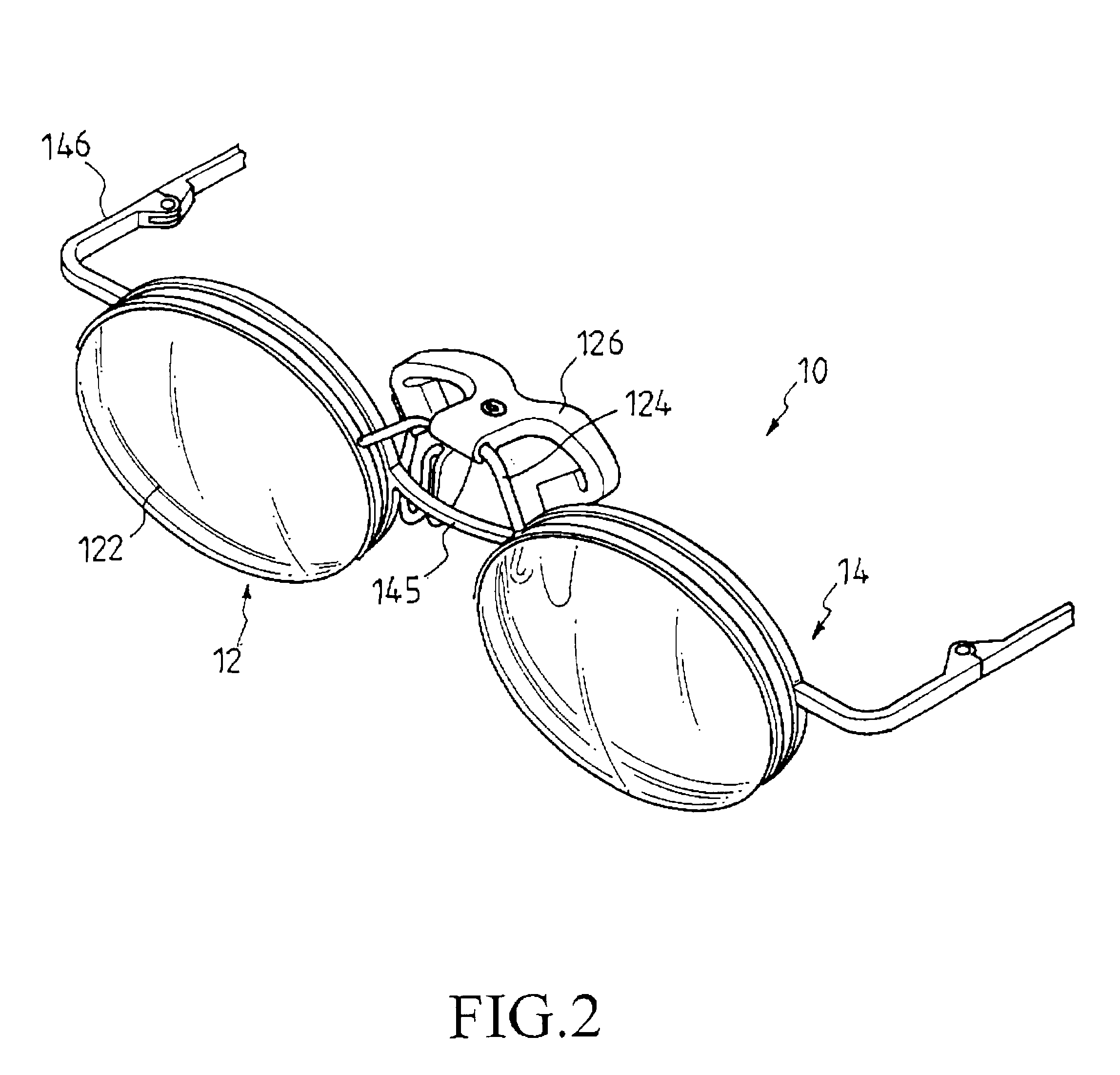
As shown in FIGS. 1 and 2 and an alternative embodiment in FIG. 5, the eyewear 10, 10' comprises an auxiliary frame 12, 12' and a main frame 14, 14' which are magnetically connected to each other.

The auxiliary frame 12, 12' comprises an auxiliary lens retaining mechanism 124, 124' for accommodating a pair of auxiliary lenses 122, 122' thereto, and an attachment mechanism 126, 126', wherein the attachment mechanism 126, 126' comprises an auxiliary magnetic apparatus preferably in the form of a pair of auxiliary magnets 1262, 1262'.

In the embodiment shown in FIGS. 1 and 2, the auxiliary lens retaining mechanism 124 includes a pivotal shaft 1242. The pivotal shaft 1242 is formed with a stopping feature preferably in the form of stopping facets 1244 around its peripheral edge. The attachment mechanism 126 is resiliently and pivotably joined to the auxiliary lens retaining mechanism 124, which includes a length-wise groove 1266 and a resilient sheet 1268 to allow the pivotal shaft 1242 o...


PUM


Abstract

The present invention discloses an eyewear comprising an auxiliary frame and a main frame which are magnetically connected to each other. In a preferred embodiment, the auxiliary frame comprises an auxiliary lens retaining mechanism for accommodating a pair of auxiliary lenses; and an attachment mechanism resiliently and pivotably joined to the auxiliary lens retaining mechanism. The attachment mechanism is provided with an auxiliary magnetic apparatus for magnetically coupling to a corresponding main magnetic apparatus on the main frame. In a more preferable embodiment, the present invention utilizes the nature of resilience of a resilient sheet to allow the main frame to be selectively stopped at different angular orientations during its pivotal action with respect to the auxiliary frame.

Description

This invention is related to an eyewear, and more particularly to a main and an auxiliary eyewear each having magnets at lens retaining mechanisms thereof for attachment.BACKGROUND OF INVENTIONAuxiliary frames with lenses have been used for decades to augment deficiencies in main frames. For example, the auxiliary frames may be for magnifying purposes, or may transform the main frames into sunglasses.For decades, people around the world have been creating numerous ingenious methods to attach the auxiliary frames onto the main frames. In one line of approaches, the auxiliary frames are clipped onto the lenses of the main frames. Not only do such clips obstruct the wearer's vision, they may scratch the lenses of the main frames. To alleviate the defect of view obstruction, there are designs using small clips at the edges of the frames. However, these small clips still create scratches on the lenses and the main frames; and attaching these auxiliary frames with small clips requires som...

Claims


Application Information

Patent Timeline
Patent Type & Authority Patents(United States)
IPC IPC(8): G02C9/00G02C9/02
CPCG02C9/00G02C9/02G02C2200/02
Inventor HUANG, DAVID
Owner HUANG DAVID
Learn More