Resonator structure embedded in mechanical structure

Inactive Publication Date: 2002-03-12
RPX CORP
View PDF7 Cites 87 Cited by
  • Summary
  • Abstract
  • Description
  • Claims
  • Application Information

AI Technical Summary

Problems solved by technology

However, the size of the cavity required to produce the desired resonant freq

Method used


Image

  • Resonator structure embedded in mechanical structure
  • Resonator structure embedded in mechanical structure
  • Resonator structure embedded in mechanical structure

Examples


Embodiment Construction

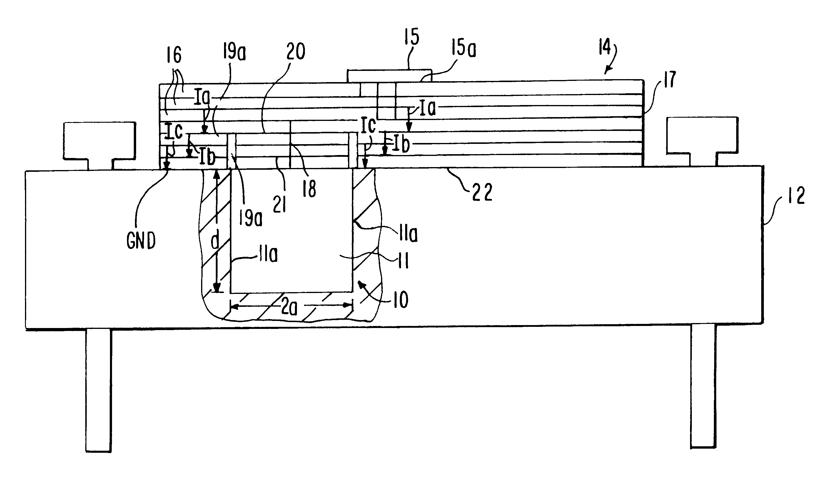
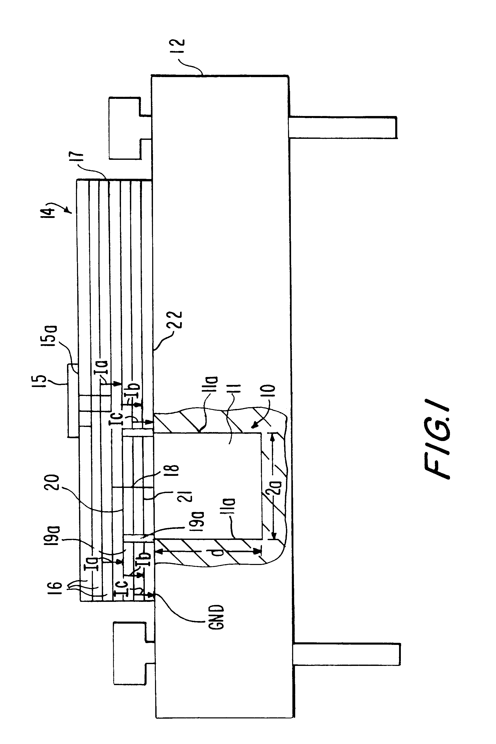
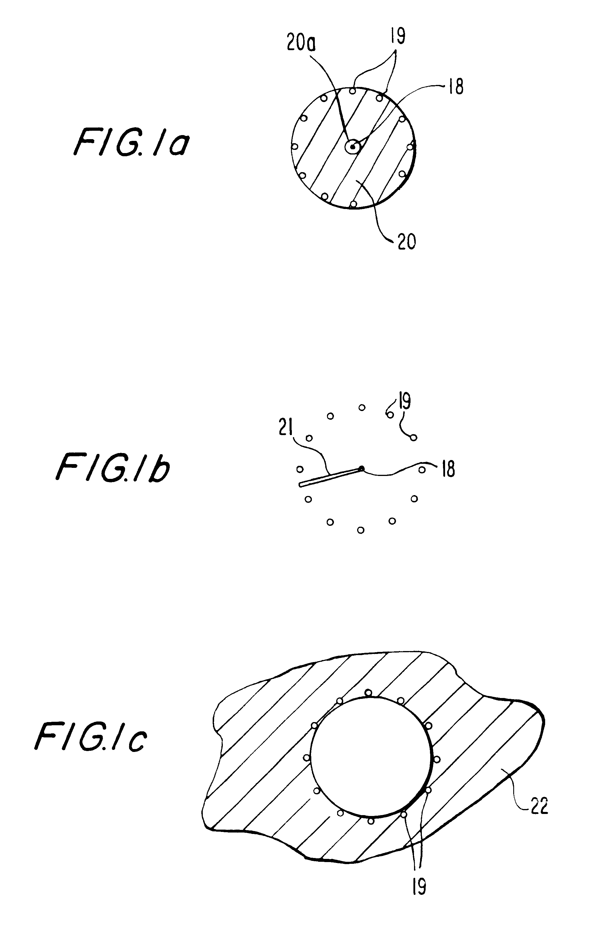
FIG. 1 shows an arrangement of a cavity 11 for a cavity resonator 10 integrated into a baseplate 12 on which a multi-chip module (MCM) 14 is mounted. The MCM 14 comprises an integrated circuit 15 mounted on a substrate 17. The integrated circuit 15 may comprise any type of circuit requiring a resonator such as, for example, a voltage controlled oscillator (VCO) or a filter. The integrated circuit 15 is connected to the cavity resonator 10 via an excitation coupling 18. The substrate 17 closes the cavity 11 and includes vias 19, i.e., passages through multiple layers of the substrate 17. The vias 19 are arranged so that the bottom of each of the vias is in communication with walls 11a of the cavity 11. The vias 19 may be, for example, 100-200 .mu.m in diameter and may be arranged along the wall 11a of the cavity 11 at a pitch of, for example, 200-450 .mu.m. The vias 19 each have a via wall 19a which extend the wall 11a of the cavity 11 inside the MCM 14. If the cavity 11 is circular,...


PUM


Abstract

An assembly for supporting a substrate of an integrated circuit and forming a cavity resonator with the substrate. The assembly includes a baseplate in which a cavity for the cavity resonator is integrally formed. A substrate is mounted over the cavity resonator in the baseplate and an excitation coupling extends into the cavity of the cavity resonator.

Description

1. Field of the InventionThe present invention relates to a resonator incorporated in a baseplate of an integrated circuit module.2. Description of the Related ArtWaveguide resonators are designed to operate at a resonant or natural frequency and store oscillating energy that is oscillating at or near the resonant frequency for time periods that are long relative to a period of the resonant frequency. Oscillating energy that is not oscillating at or near the resonant frequency is not stored for an appreciable amount of time. Resonators are described in terms of their quality factor Q which is dependent on a ratio of the maximum stored energy to the energy dissipated per cycle at a given frequency. Cavity resonators generally exhibit the highest Q values. However, the size of the cavity required to produce the desired resonant frequency makes it difficult to mount and connect to an integrated circuit module. For this reason, thin film resonators and dielectric resonators are used ins...

Claims


Application Information

Patent Timeline
IPC IPC(8): H01P7/00H01P7/06
CPCH01P7/065
Inventor KOIVISTO, MARKKUSALMELA, OLLISOMERMA, HANSJOKIO, KALLE
Owner RPX CORP
Why Eureka
Try Eureka