
Serial bus hub

Inactive Publication Date: 2002-03-12
HEWLETT PACKARD DEV CO LP
View PDF22 Cites 22 Cited by
  • Summary
  • Abstract
  • Description
  • Claims
  • Application Information

AI Technical Summary

Problems solved by technology

This entanglement of cables presents a drawback because it gives rise to the general difficulty of determining which cable connection on the rear of the CPU supports the corresponding peripheral device.
This particular drawback is compounded by the connectors being closely positioned to each other on the rear of the CPU.
Even if the connecting wires are kept organized, they still tend to be annoying and unsightly to the user.
Furthermore, there is limited spacing at the rear of the CPU for the many peripheral connections.
This leads to another deficiency in terms of accessibility to the connectors located on the rear of the CPU.
The connector locations on the rear of the CPU do not always provide for easy access and installation of the cables connected to a peripheral device.
It is common for an installer to have to reach behind the CPU in order to make a desired connection, which is sometimes performed in an awkward orientation.
Another shortcoming that results from connecting peripheral devices directly to the CPU is the added necessity of requiring close proximity of the CPU to the workspace since peripheral devices come with a limited amount of interface cabling.
In other words, the peripheral devices cannot be used a large distance from the CPU.
First, is the unsightliness of the resulting cables converging to a limited space on the rear of the CPU.
Second, connector accessibility does not always provide for easy access and installation of the peripheral devices on the rear of the CPU.
And third, the CPU must be in close proximity to the workspace since the peripheral devices come with a limited amount of cabling.

Method used


Image

  • Serial bus hub
  • Serial bus hub
  • Serial bus hub

Examples


Embodiment Construction

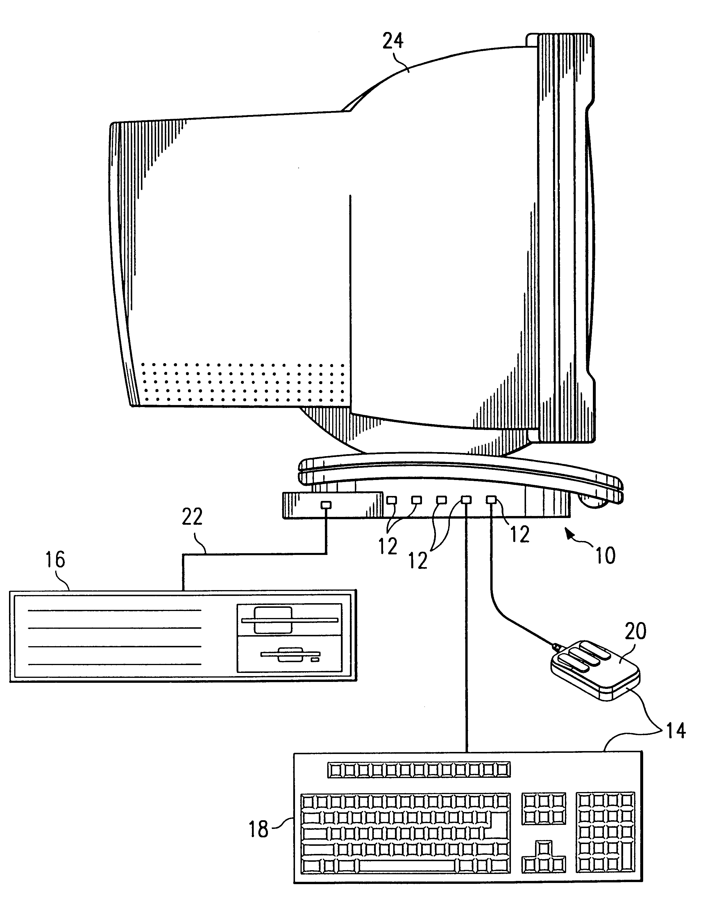
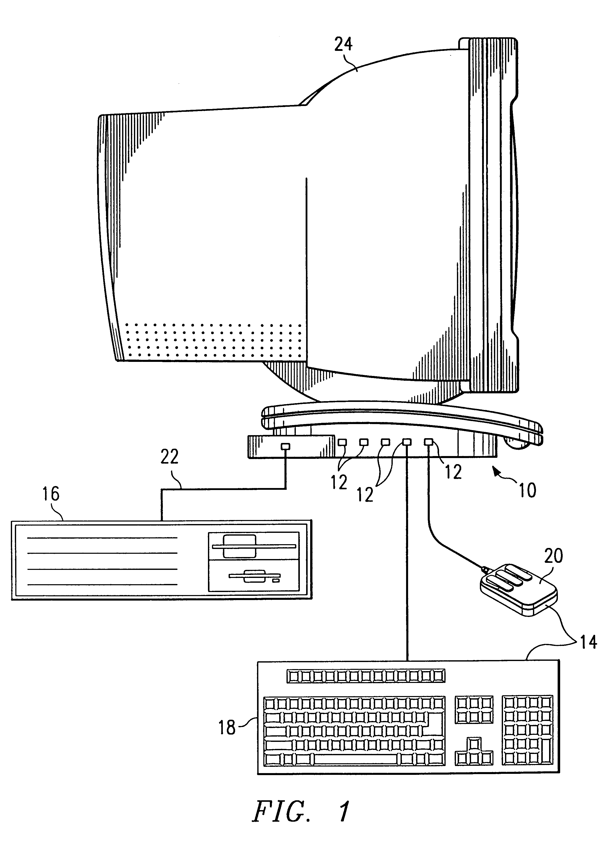
Referring to FIG. 1, an exemplary embodiment of a monitor base which serves as a serial bus hub 10 is depicted. The monitor base serial bus hub 10 has a plurality of ports 12 to provide a means for connecting a plurality of peripheral devices 14. Connection is made directly to the monitor base hub 10 instead of on the rear of a central processing unit (CPU) 16.

As shown, a keyboard 18 and a mouse 20 are representative of the types of peripheral devices 14 that can be connected to the monitor base hub 10. Other peripheral devices 14 which can communicate via the monitor base hub 10 to the CPU over a single serial bus 22 may be connected to the monitor base hub 10 via the plurality of ports 12. These other types of peripheral devices are discussed in more detail below.

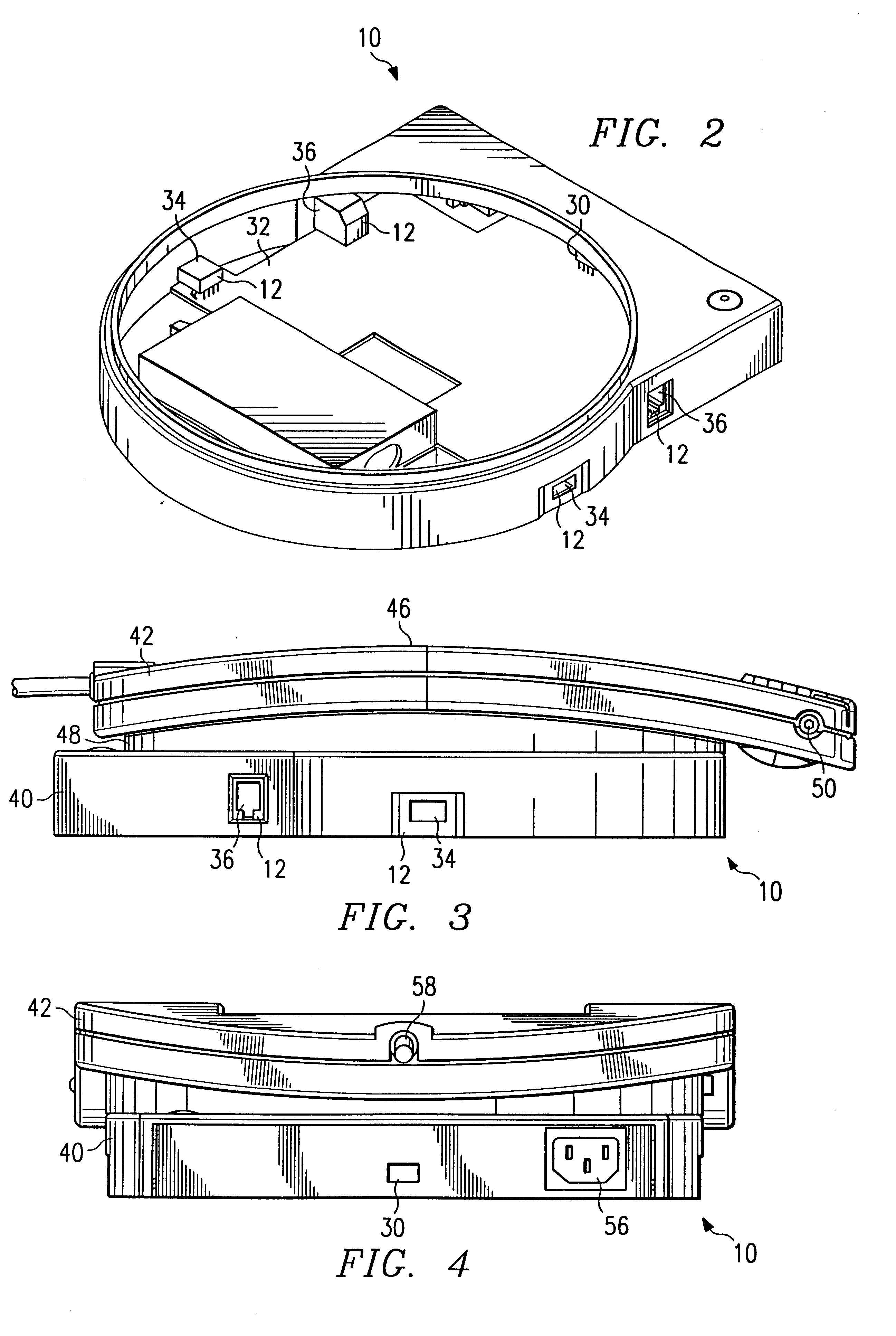
Although the monitor base hub 10 could be a variety of shapes and sizes, the preferred monitor base hub 10 has a substantially flat upper surface and an adapter means (not shown) to connect to and support a monitor 24. In...


PUM


Abstract

The present invention relates to a monitor base that comprises a serial bus hub having a plurality of ports connected to the hub for interface with a plurality of peripheral devices. With the ports located on the monitor base hub, a computer system's peripheral devices, i.e., keyboard, mouse, printer, scanner, video camera, etc., are connected to the monitor base hub instead of on the rear of the central processing unit.

Description

1. Technical Field of the InventionThe present invention relates t o a centralized distribution of a serial data bus for a plurality of peripheral devices. In particular, the present invention relates to a monitor base that comprises a serial bus hub having a plurality of ports.2. Description of Related ArtPeripheral device s designed to operate with home and office computer systems are typically connected on the rear of the computer system's central processing unit (CPU). The CPU in turn provides the appropriate interface and control for these peripheral devices through individualized connections. With the proliferation of peripheral devices designed to operate with a computer system, an entanglement of cables can easily form when a number of peripheral devices are connected to the CPU. This entanglement of cables presents a drawback because it gives rise to the general difficulty of determining which cable connection on the rear of the CPU supports the corresponding peripheral dev...

Claims


Application Information

Patent Timeline
IPC IPC(8): G06F1/16G06F1/18G09F9/00H01R25/00
CPCG06F1/1601G06F2200/1611
Inventor MARTIN, RANDALL W.
Owner HEWLETT PACKARD DEV CO LP
Learn More