Electric screen device

Inactive Publication Date: 2002-03-19
HITACHI ZOSEN CORP
View PDF10 Cites 8 Cited by
  • Summary
  • Abstract
  • Description
  • Claims
  • Application Information

AI Technical Summary

Benefits of technology

According to the above arrangement, since the product of the peak value of the intensity of the electric field produced between the electrode assemblies disposed on opposite sides of the water channel and the

Problems solved by technology

According to the electric screen device described above, however, the off-time is relatively long, which fact

Method used


Image

  • Electric screen device
  • Electric screen device
  • Electric screen device

Examples


Embodiment Construction

The invention will now be described in more detail with reference to the accompanying drawings.

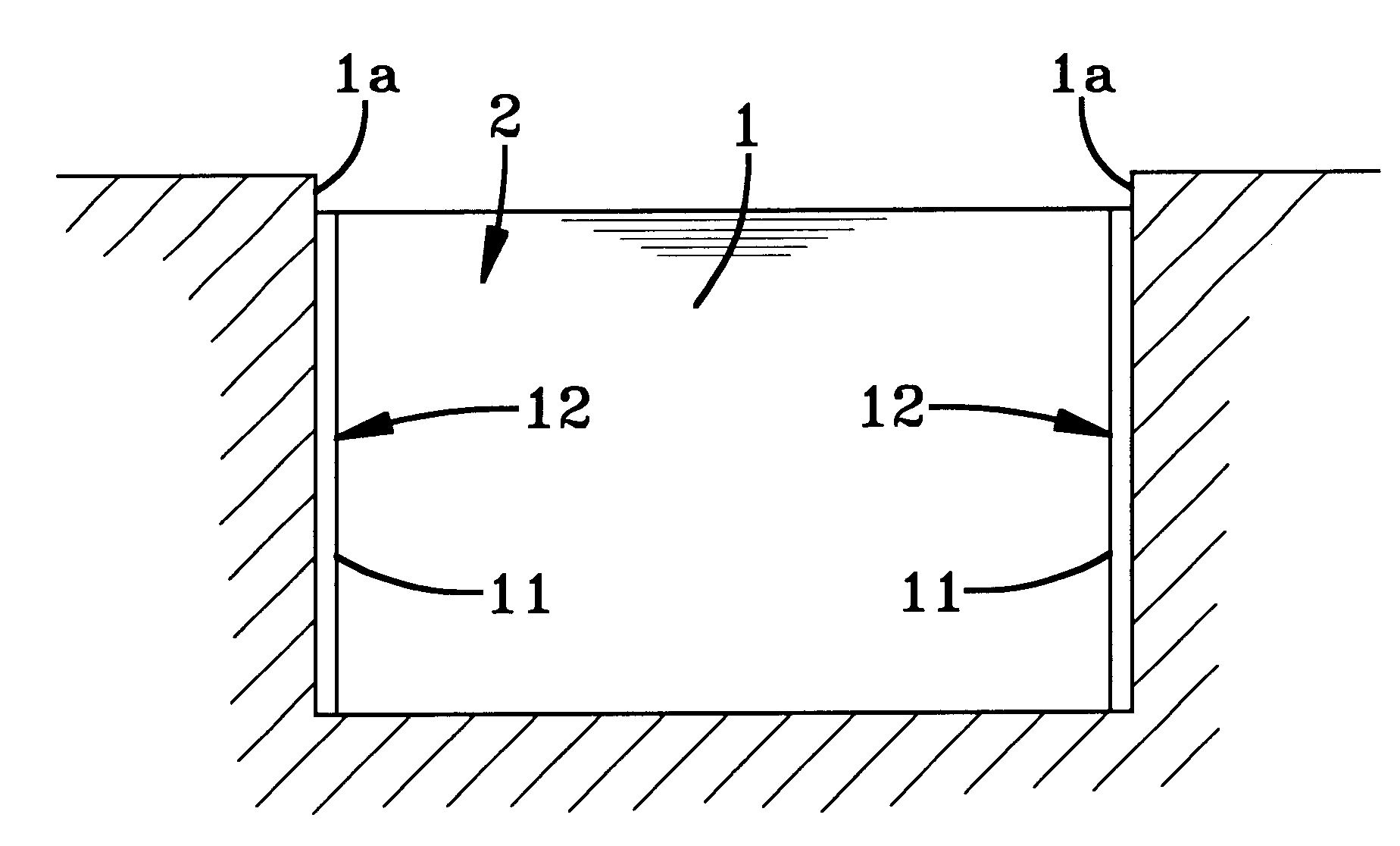
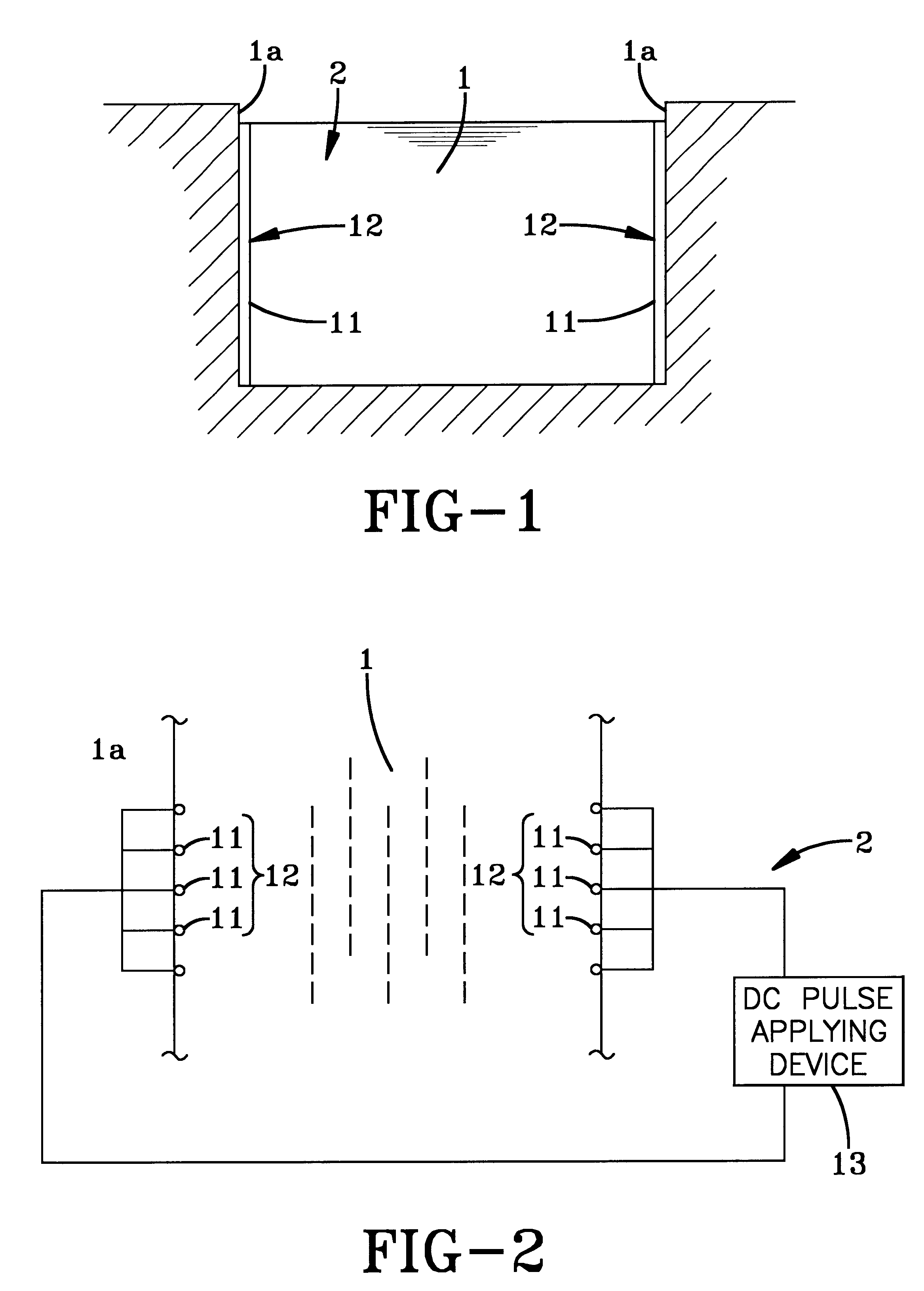
FIG. 1 is a sectional view of a water intake channel provided with an electric screen device, and FIG. 2 is a plan view thereof.

As shown in FIGS. 1 and 2, the numeral 1 denotes a water intake channel leading to a port for taking in cooling water, e.g., in a power plant, with an electric screen device 2 installed somewhere between the ends of said channel.

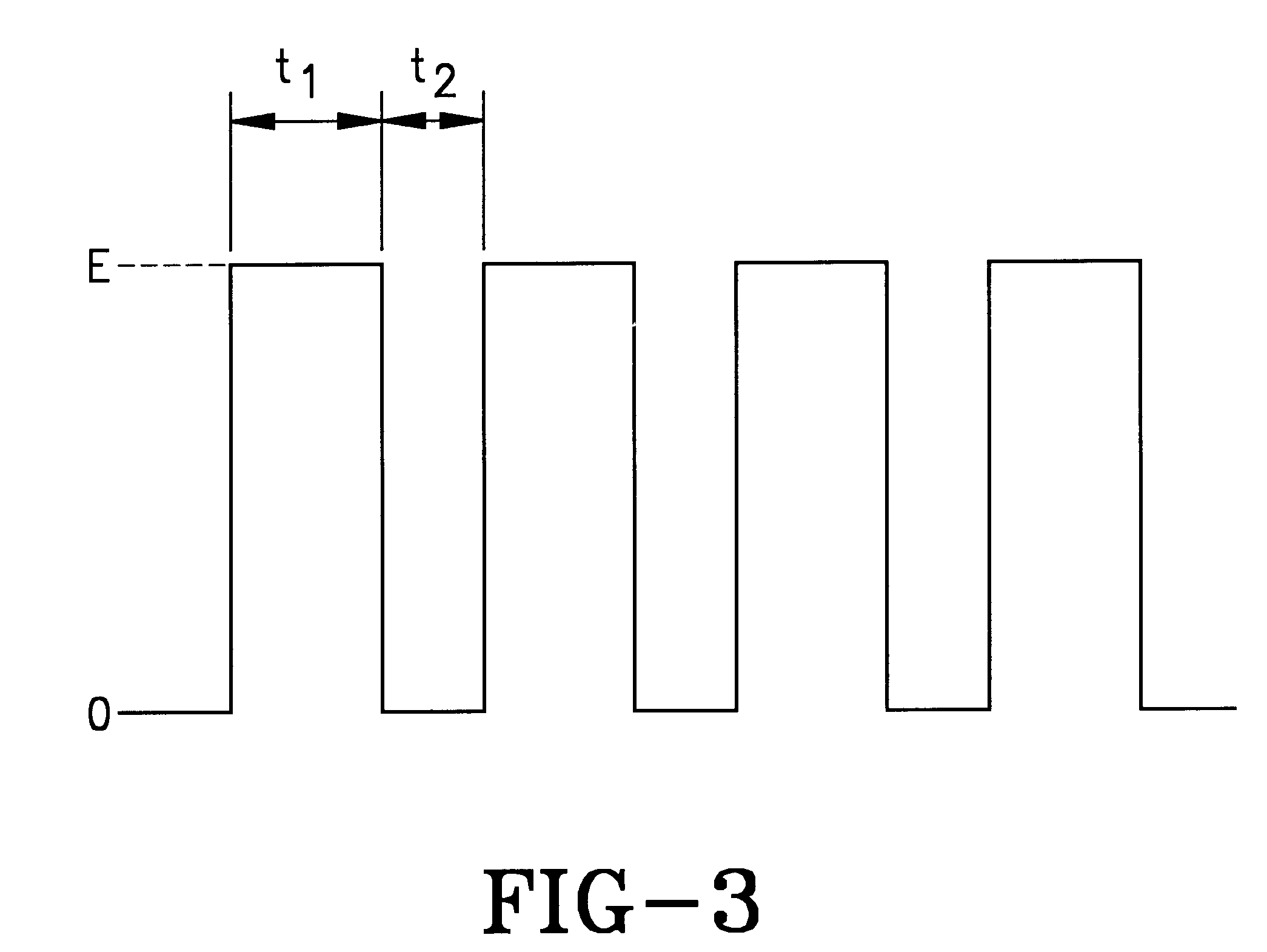
This electric screen device 2 comprises a pair of electrode assemblies 12, 12 disposed on opposite side walls la of the water intake channel 1, each assembly being composed of a plurality of electrode rods 11 disposed at predetermined intervals, and a dc pulse applying device 13 for applying dc pulses between said electrode assemblies 12, 12 under a predetermined voltage and at predetermined intervals of time. Further, the electrode rods 11 are vertically installed.

And dc pulses as shown in FIG. 3 are applied to said dc pulse applying devi...


PUM


Abstract

An electric screen device for preventing creatures from intruding into a water channel, which comprises a pair of opposed electrode assemblies disposed on opposite sides of a water intake channel, and a dc pulse applying device 13 for applying dc pulses between the electrode assemblies. In such electric screen device, the product of the peak value of the intensity of an electric field produced between the electrode assemblies by the dc pulse applying device and the body length of creatures to be prevented from intrusion into the water channel is not less than 0.1 V, the dc pulse applying time is within the range of 2-200 msec, and the duty factor of the dc pulse is not more than 0.5.

Description

The present invention relates to an electric screen device for preventing creatures, such as fishes and shellfishes, from intruding into a water intake port, i.e., a water intake channel or the like in a power plant or the like.To prevent creatures, such as fishes and shellfishes, from intruding into a water intake port in a power plant, a water intake channel is provided with an electric screen device.Conventionally, this electric screen device comprises a pair of opposed electrode assemblies disposed on opposite side walls of the water intake channel, and a voltage applying device for applying dc or ac voltage between said electrode assemblies at predetermined intervals of time.Thus, an electric screen is formed by a predetermined voltage applied between said electrode assemblies at predetermined intervals of time by the voltage applying device.The applied voltage is of a value such that the product of the peak value of the intensity of an electric field and the voltage applying t...

Claims


Application Information

Patent Timeline
IPC IPC(8): H05C1/00H05C1/04
CPCH05C1/04
Inventor MAEHATA, HIDEHIKOTSUKAHARA, MASANORITAMAKOSHI, DAISUKESUZAKI, TOMOHIKOISAWA, YUTAKA
Owner HITACHI ZOSEN CORP
Why Eureka
Try Eureka