Optical design for a reflector for reflecting light beams

a technology of optical design and reflector, which is applied in the direction of optics, mountings, lighting apparatus, etc., can solve the problems of not always being achieved, and the deviation of the circular form of the light field is therefore not possible with many means

Inactive Publication Date: 2002-03-26
AUER LIGHTING
View PDF5 Cites 28 Cited by
  • Summary
  • Abstract
  • Description
  • Claims
  • Application Information

AI Technical Summary

Benefits of technology

Another possibility consists of pairing uneven shapes with one another. An area of reflector inner surface can be formed from spherical facets, for example, whi...

Problems solved by technology

This is not always accomplished, however.
It may be oval or similar to the shape of a right angle, which is undesired.
With use o...

Method used


Image

  • Optical design for a reflector for reflecting light beams
  • Optical design for a reflector for reflecting light beams
  • Optical design for a reflector for reflecting light beams

Examples


Embodiment Construction

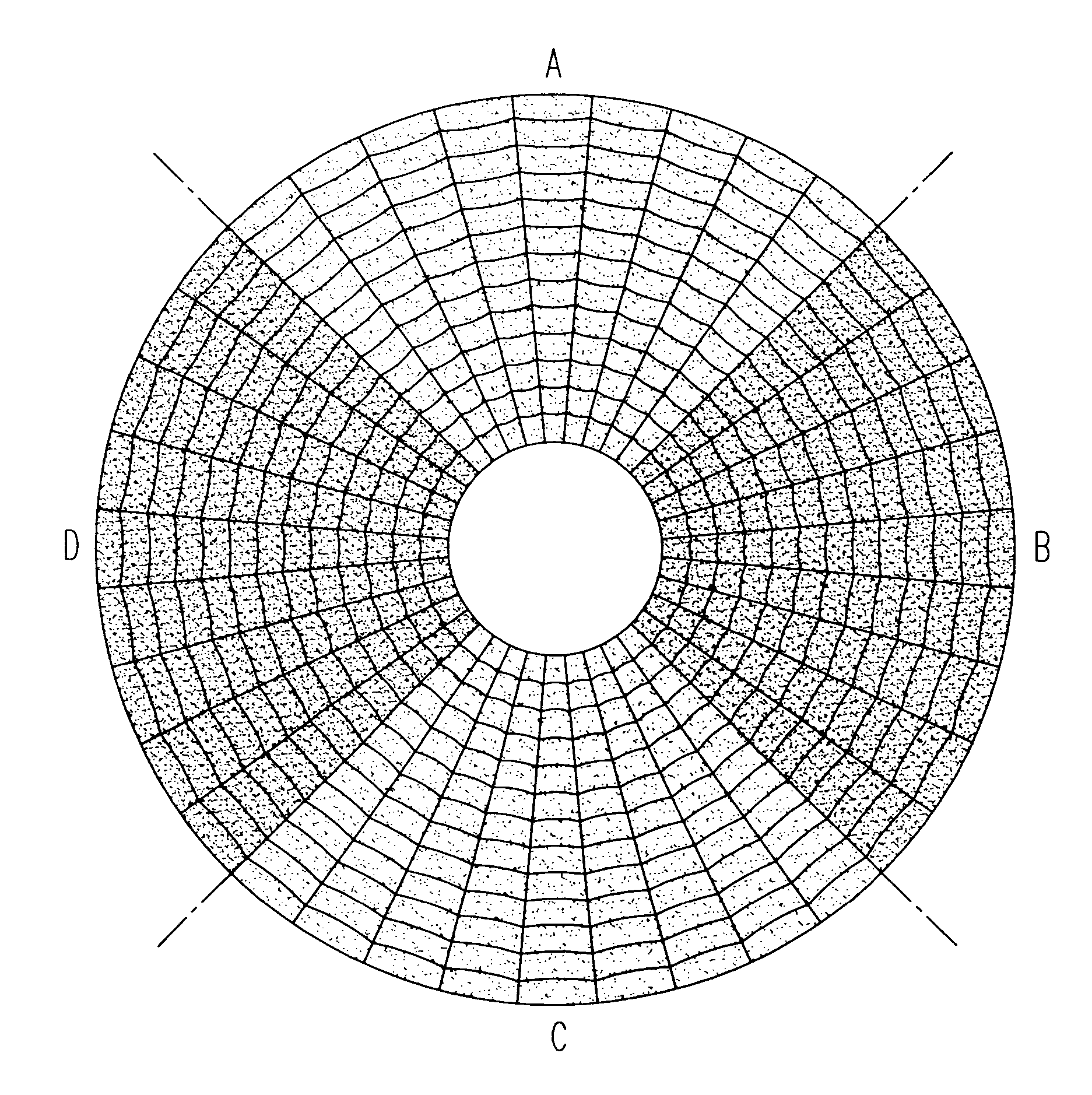
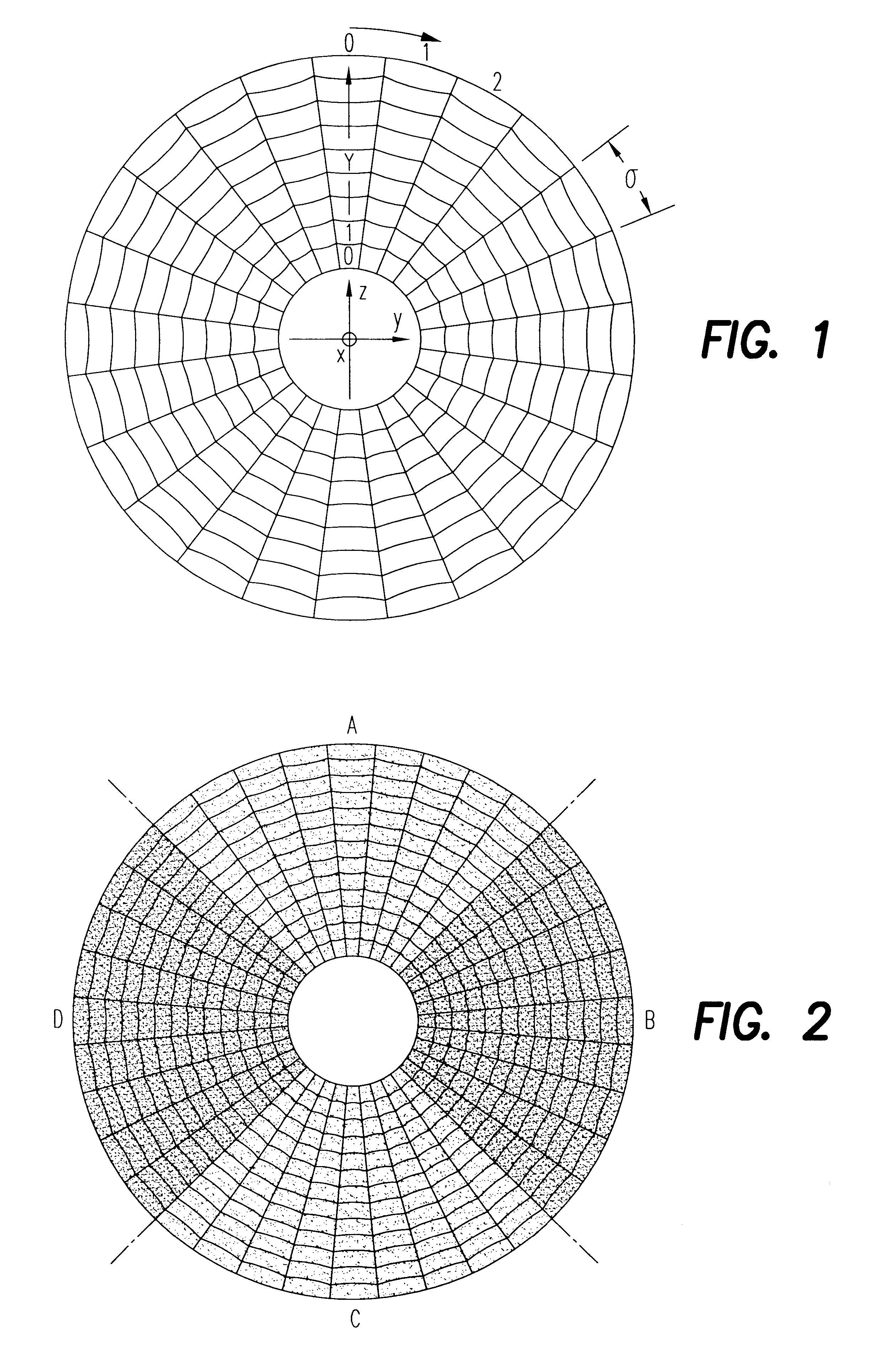
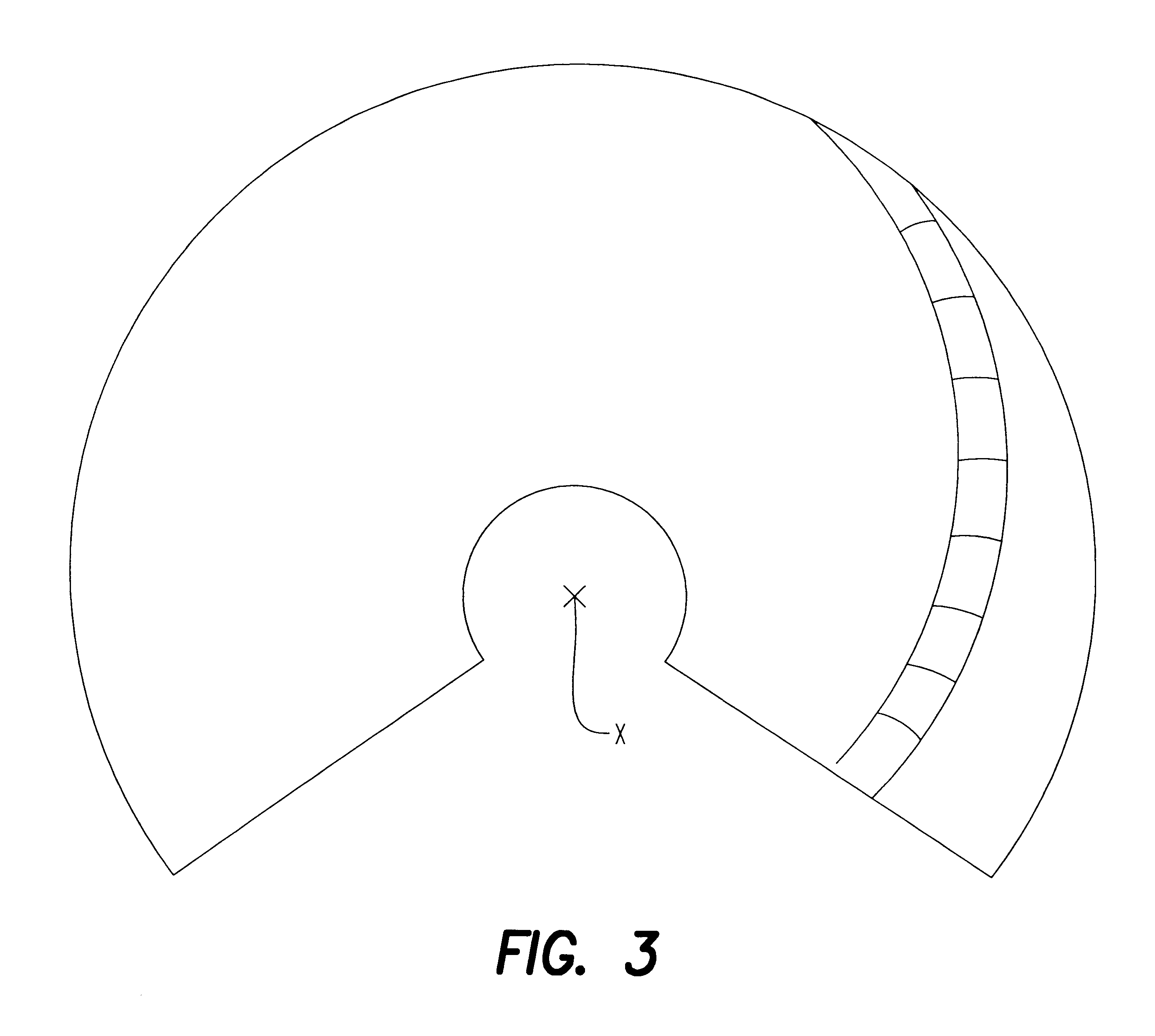
In the reflector illustrated in FIG. 1 the facets are arranged in rows which run concentrically to the x axis. At the same time the facets are arranged in columns and may be spherical or cylindrical in shape.

The radii of the facets, that is, the radii of the spheres or the cylinders, vary within a row of facets corresponding to the size of the dihedral angle at which the facet `sees` the illuminant. In the case of a large dihedral angle and associated greater light scatter a lesser curvature of the facet surface is accordingly selected, thus a greater facet radius, and vice versa. If the dimensions of the illuminant are greater in the direction of the y axis than in the direction of the z axis, the radii of the facets must be greater in two columns, which lie on the z axis, than the radii of the facets in both columns which lie on the y axis. The radii of the facets in the in-between columns are to be selected appropriately between both these extreme values.

In practice the following...


PUM


Abstract

The invention relates to a reflector having reflection surface with facets for reflecting light beams and for generating a light field with a hollow basic element which presents a first end for accommodating an illuminant (mounting end), as well as a second end which represents a light outlet aperture, whereby for generating a specific light field contour with a given form of illuminant the forms of individual facets and their position relative to the optical axis of the reflector are selected specifically.

Description

(1) Field of the InventionThe present invention relates to the optical design of a reflector in the form of facets for reflecting light beams. Such reflectors are utilised, for example, for lighting for general illumination purposes. They have found wide application in fibre optics, for example. They are also utilised for light supply in video projectors or in spotlights which generate a sharply defined light field (so-called tracking spotlights).(2) Description of Related ArtSuch reflectors generally have an elliptical, parabolic or conical basic contour. In many cases an optical design in the form of facets is overlaid on this basic contour, in order to improve the uniformity of the light field and / or to increase the size of the light field.In general, the aim is to have reflectors of this kind produce a circular light field. This is not always accomplished, however. The reason for this is that the illuminants being utilised are not rotationally symmetrical. The outcome of this is...

Claims


Application Information

Patent Timeline
IPC IPC(8): F21V7/04F21V7/00G02B5/10F21V7/09
CPCF21V7/04F21V7/09F21V7/048
Inventor KITTELMANN, RUDIGERWAGENER, HARRY
Owner AUER LIGHTING
Why Eureka
Try Eureka