Al technical title is built by PatSnap Al team. It summarizes the technical point description of the patent document.
a vacuum dusting and attachment device technology, which is applied in the direction of vacuum cleaners, carpet cleaners, floor cleaners, etc., can solve the problems of insufficient prior art reference, inaccurate and flexible feathering arrangement of prior art for efficiently dislodging dust and like particles, and many other issues
Inactive Publication Date: 2002-04-16
CARTER WILLIAM B
View PDF16 Cites 31 Cited by
Summary
Abstract
Description
Claims
Application Information
AI Technical Summary
This helps you quickly interpret patents by identifying the three key elements:
Problems solved by technology
Method used
Benefits of technology
Problems solved by technology
In addition, all of the relevant prior art heretofore known suffer from a number of disadvantages.
None of the prior art references adequately address the problem of marshaling dust and particle debris to a central body for suction and evacuation.
Also, the prior art has not provided an accurate and flexible feathering arrangement for efficiently dislodging dust and like particles, but relied upon hard or substantially inflexible bristles or one-direction, hard, feathering of one basic length and dimensioning, secured to point in only one direction, and secured at one location only or at limited locations on inferior designed core bodies.
Additionally, none of the prior art devices in this area of technology have employed any configuration, or dimensioning or sizing, of feathering, except those of conventional dusters utilized in the art without vacuum cleaning devices.
Further, none of the prior art devices appear to have a central body or core which is constructed of malleable and flexible soft metal, alloy, polymer or composite; and which can be dimensionally adjusted by virtue of such construction materials, while retaining structural and positional integrity.
These and other disadvantages, structurally and functionally, of the prior art, will become apparent in reviewing the remainder of the present specification, claims and drawings.
Method used
Image
Click on the blue label to locate the original text in one second.
Reading with bidirectional positioning of images and text.
Examples
Embodiment Construction
The following description of the preferred embodiments of the concepts and teaching of this present invention is made in reference to the accompanying drawing figures which constitute preselected illustrated examples of the structural and functional elements of the present invention, among many other examples existing within the scope and spirit of the present invention.
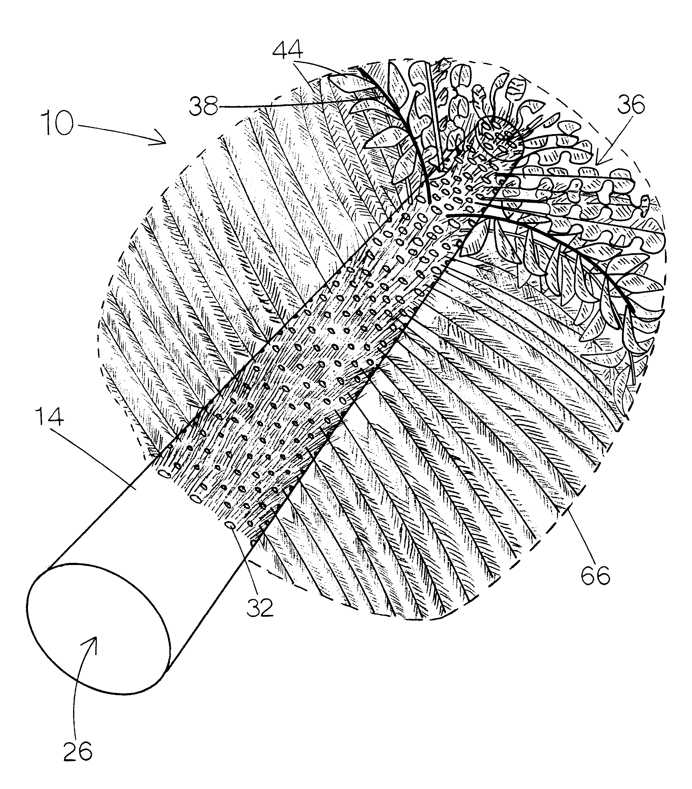
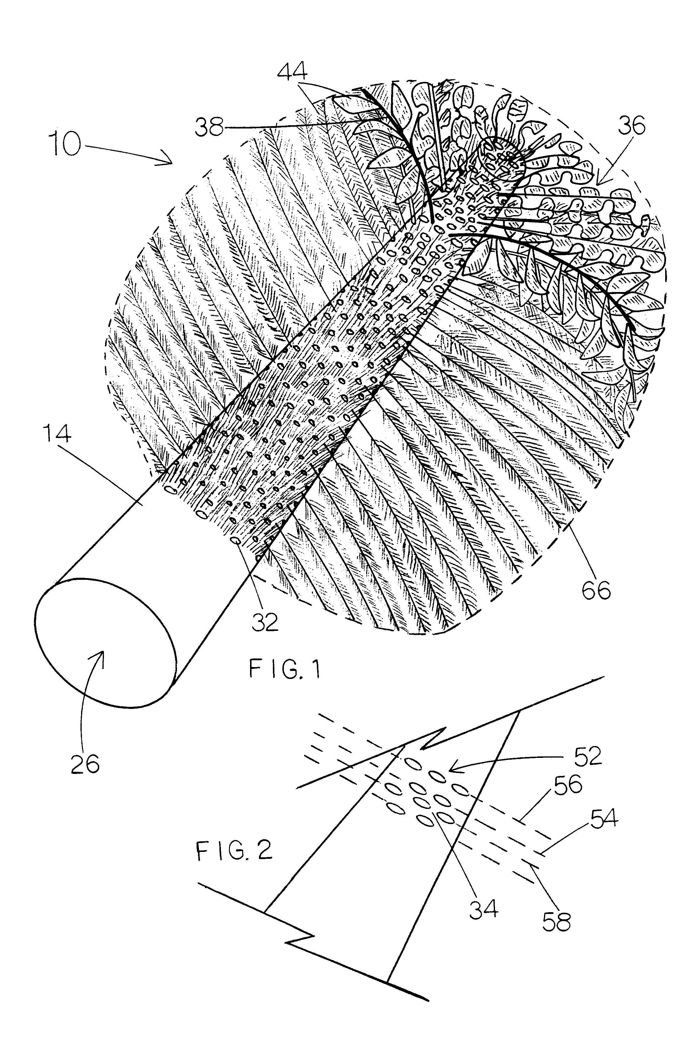
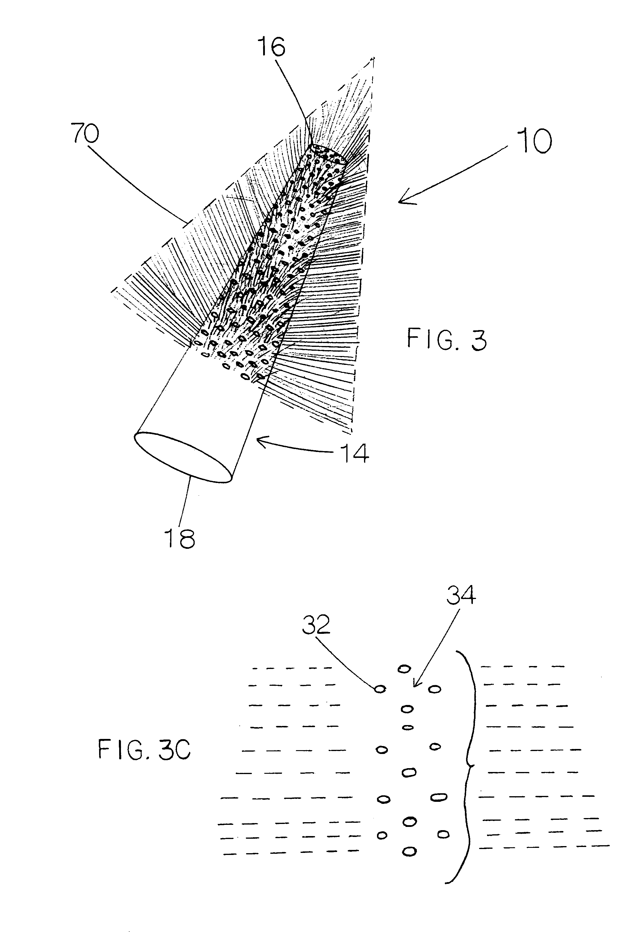
Referring now to the drawings; FIGS. 1, 2, 3, 3A, 3B, 3C, 4, 4A, 4B, 5, 6, 6A, 6B, 7, 8, 9, 10, 11A, 11B, 12, and 13, thereof, there is shown a vacuum and blower dusting and dislodging attachment device 10, of the present invention, referred to herein as the DAD 10 (Dusting Attachment Device).
The DAD 10 is utilized in interaction with a cleaning system line 12, such as a suction-type vacuum cleaner or blower-cleaning system, each having an extended, exposed or extendable hose or communication line; such as those, and related systems, conventionally available.
The DAD 10 is provided with a core unit 14, having an apex ...
PUM
Abstract
A dusting attachment device is disclosed for use in interaction with a line or connection hose of a suction or blowing type cleaning system. The invention is provided with a core unit with base and apex ends and three lengthwise oriented portions. The core has a cone, truncated cone, pyramid or truncated pyramid shape, in preferred embodiments. The invention's core is provided with a selected functional patterning of air apertures which extend through the core's outboard and inboard surfacing and communicate with the core's central air channel. As patterned, each of the air apertures have an interstitial space portion between each other, which sets forth air apertures and interstitial spaces on the outboard and inboard surfaces of the core's apex end and first two portions. The apertures are also arranged in sequence and position in relation to one another. A feathering system is provided having a number of individual feather components, where each of the feather components are attached to the interstitial spaces of the core's outboard surfacing. The invention is fabricated so that each feather component is dimensioned to be part of an overall configuration shape of the feathering system; and the core unit is fabricated from malleable, formable or positionable material or fabric having position integrity. The third portion provides the end opening of the air channel and is positioned / installed in interaction with a line of a cleaning system.
Description
1. Field of the InventionThe present invention relates to apparatus, method and system for providing a dusting attachment device, which is installed on a suction-type vacuum cleaner and functions to equalize air flow current while providing a favorable dusting or dislodging surface.2. Background InformationThose references found in the process of a U.S. patent search, having some relation in the prior art to technology attempting to address dusting and cleaning functions, or marshalling of debris in relation to another cleaning assembly, of those references found, include United States Patents to Miller, U.S. Pat. No. 5,123,142; Hamilton, U.S. Pat. No. 2,198,339; Palomino, Jr., U.S. Pat. No. 5,074,008; Smith, Jr., U.S. Pat. No. 4,972,541; Farmer, U.S. Pat. No. 4,198,727; Sorenson, U.S. Pat. No. 5,692,263; El Omary, U.S. Pat. No. 5,115,765; and Na, U.S. Pat. No. 5,652,997.Miller '142 discloses a Vacuum Operated Cleaner Attachment. Disclosed therein is a cleaner attachment for use wit...
Claims
Application Information
Patent Timeline
Application Date:The date an application was filed.
Publication Date:The date a patent or application was officially published.
First Publication Date:The earliest publication date of a patent with the same application number.
Issue Date:Publication date of the patent grant document.
PCT Entry Date:The Entry date of PCT National Phase.
Estimated Expiry Date:The statutory expiry date of a patent right according to the Patent Law, and it is the longest term of protection that the patent right can achieve without the termination of the patent right due to other reasons(Term extension factor has been taken into account ).
Invalid Date:Actual expiry date is based on effective date or publication date of legal transaction data of invalid patent.