Crate assembly and improved method

a crate and assembly technology, applied in the field of improved crate assembly, can solve the problem that none of the foregoing prior art teaches a crate assembly which is capabl

Inactive Publication Date: 2002-04-16
HOWARD INDS
View PDF18 Cites 37 Cited by
  • Summary
  • Abstract
  • Description
  • Claims
  • Application Information

AI Technical Summary

Problems solved by technology

None of the foregoing prior art teaches a crate assembly which is capable of shipping articles of com...

Method used


Image

  • Crate assembly and improved method
  • Crate assembly and improved method
  • Crate assembly and improved method

Examples


Embodiment Construction

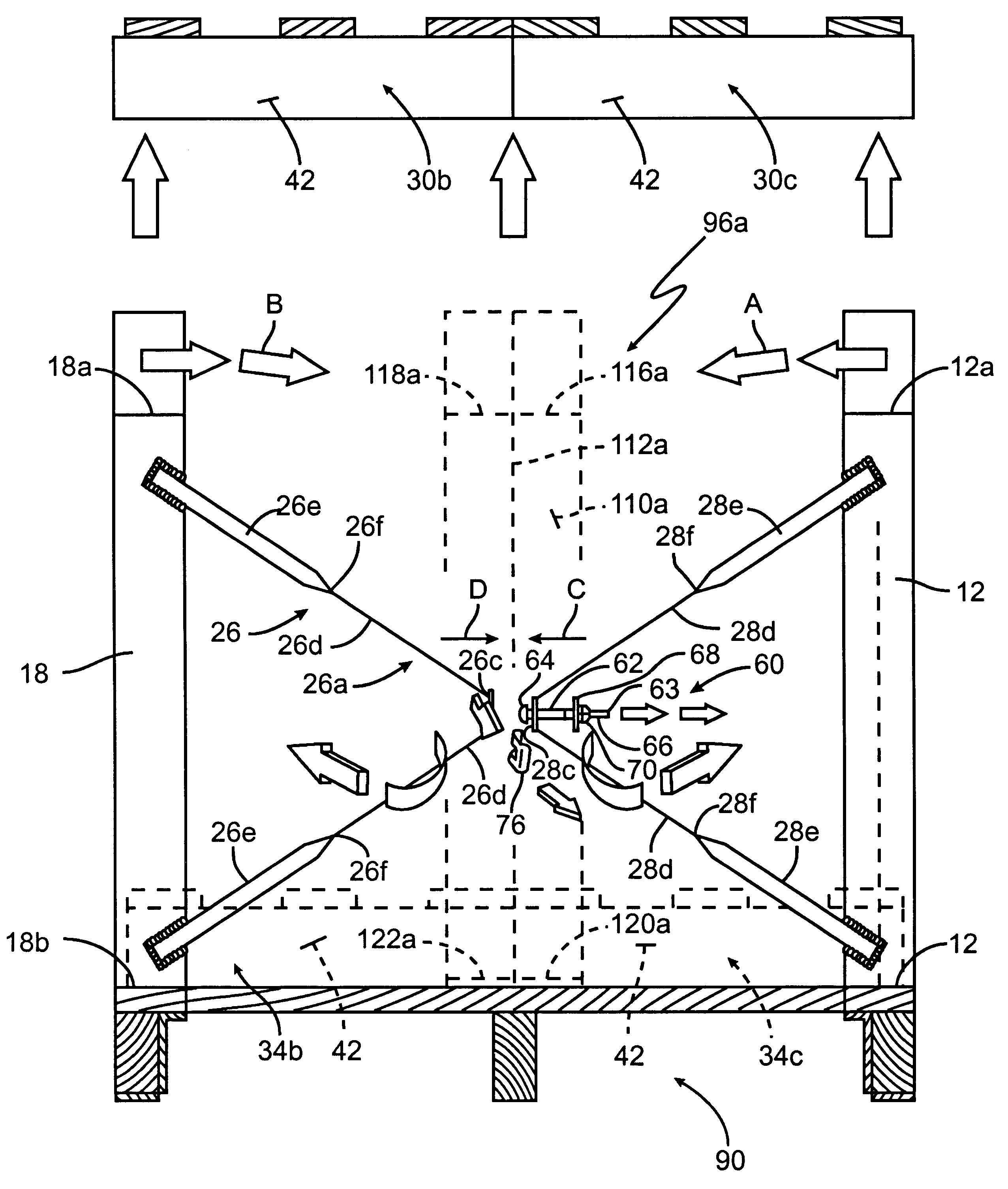
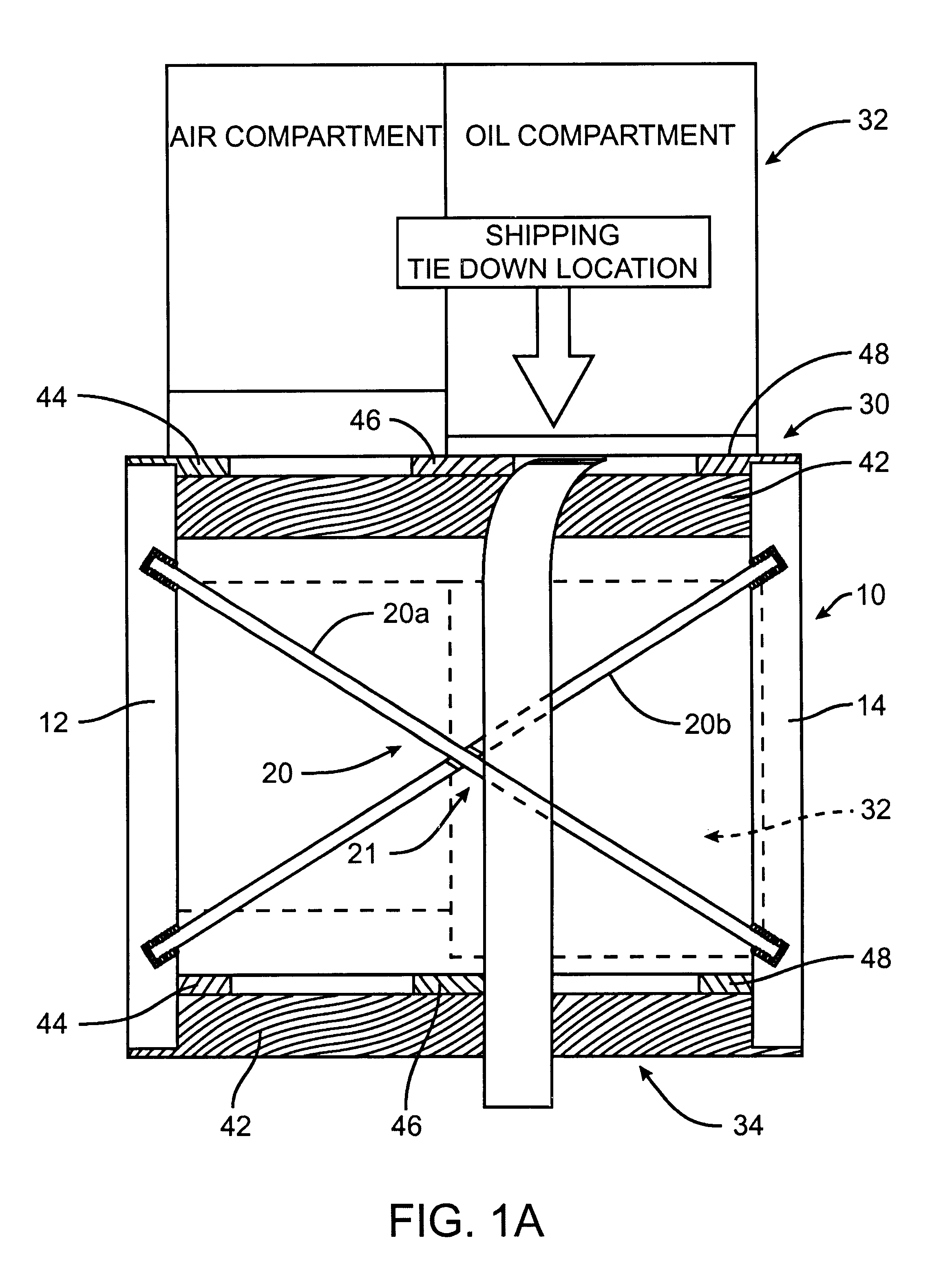
Referring in detail now to the drawings wherein similar parts of the invention are identified by like reference numerals, there is seen a crate assembly, generally illustrated as 10, having corner support members 12, 14, 16 and 18 which are manufactured from any suitable strong and sturdy material, such as iron, steel or similar metal or metallic alloy. Comer support members 12 and 14 (see FIG. 1A) are coupled or interconnected together by a brace assembly 20. Similarly, corner support members 14 and 16 and corner support members 16 and 18 are also coupled or interconnected together by brace assemblies 22 and 24, respectively (see FIGS. 1B and 1C). As best shown in FIG. 2, corner support member 18 has a tension brace assembly 26 secured thereto. Comer support member 12 has a similar tension brace assembly 28 bound thereto. Tension brace assemblies 26 and 28 are essentially mirror images of each other and are interconnected by a connecting assembly, generally illustrated as 29, when ...


PUM

PropertyMeasurementUnit
Structureaaaaaaaaaa
Tensionaaaaaaaaaa

Abstract

A crate assembly having a base, a first support member secured to the base and having a first shelf and a second support member secured to the base and having a second shelf. The crate assembly additionally includes a third support member secured to the base and having a third shelf and a fourth corner support member secured to the base and having a fourth shelf. A generally centric support member is secured to the base and includes a structure defining at least one generally centric shelf. A first brace assembly is connected to the first support member and a second brace assembly is connected to the fourth support member. A connecting assembly is releasably engaged to the first brace assembly and to the second brace assembly. A container assembly including the crate assembly supporting a pallet. A method is provided for transporting transformers with the crate assembly.

Description

1. Field of the InventionThe present invention relates to an improved crate assembly that is capable of employing more than two (2) pallets(e.g. four (4) or eight (8) pallets, etc.) for transporting articles of commerce. More specifically, the present invention provides an improved container assembly including an improved crate assembly and method for transporting articles of commerce, such as transformers and the like.2. Description of the Prior ArtA patentability investigation was conducted and the following U.S. Patents were discovered: U.S. Pat. No. 2,692,064 to Koester; U.S. Pat. No. 3,372,855 to Smith; U.S. Pat. No. 3,557,855 to Weingarten; U.S. Pat. No. 4,467,922 to Rowley; U.S. Pat. No. 4,614,277 to Fourie et al.; U.S. Pat. No. 5,058,747 to Decroix et al.; U.S. Pat. No. 5,069,338 to Gigsby; U.S. Pat. No. 5,501,334 to Przytulla et al.; and U.S. Pat. No. 5,507,392 to Schutz.U.S. Pat. No. 2,692,064 to Koester, teaches a shipping container for the storage and the transportation ...

Claims


Application Information

Patent Timeline
IPC IPC(8): B65D19/38
CPCB65D19/385
Inventor ESSARY, MARK S.
Owner HOWARD INDS
Why Eureka
Try Eureka