Transportation container

a technology for transporting containers and containers, applied in the field of transporting containers, can solve the problems of container clinging to one another due to self-weight, container lids are prone to being lost, and cannot be laid on one another during transportation

Inactive Publication Date: 2002-05-07
TOYOTA TSUSHO
View PDF5 Cites 19 Cited by
  • Summary
  • Abstract
  • Description
  • Claims
  • Application Information

AI Technical Summary

Benefits of technology

Another object of the invention is to provide a transportation container which can easily be detached from another container even when a large number of containers are laid one upon another.
According to the above-described construction, the arms of each handle are mounted on the outer faces of the side walls of the body. When each handle is rotated outside the body, one container can be fitted into another container to be laid upon another. Consequently, since the containers are laid one upon another to be kept in safekeeping when not used for transportation, a space required for safekeeping can be saved.
When products are put into the containers, each handle is rotated inward so that each engaging portion engages the upper end of the side wall of the body. As a result, since the grip portion of each handle extends across the open upper end of the body, the bottom of one container is placed on the grip portions of another container, whereby the containers can be laid one upon another. Further, each grip portion is located lower than the upper end of the body when each engaging portion has engaged the upper end of the body. Accordingly, the bottom of the container laid upon another container is fitted into the interior of the lower container. Consequently, even if the containers are slid more or less during transportation, the bottom of the upper container strikes against the inside of the upper end of the body such that the containers are prevented from falling down.
In a preferred form, the transportation container further comprises a stopper protruding from an upper outer face of one of the side walls of the body. In this construction, when the body of one transportation container is fitted into the body of another transportation container so that the containers are laid one upon the other, the stopper of said other container strikes against an upper end of one of the side walls of said one container such that a space is defined between the underside of said one container and the bottom of said another container. When one container is fitted into another container to be laid upon the latter, a space is defined between the bottoms of the containers laid one upon another. Consequently, the containers can be prevented from clinging to one another, whereupon the containers are not easily separated from one another.
In another preferred form, each arm includes a stepped portion dividing each arm into an upper half portion and a lower half portion both extending lengthwise with respect to each arm, and the lower half portion of each arm of one container is placed inside the upper half portion of each arm of another container when said one container is fitted with said another container to be laid upon said another container. When one container is fitted with another container thereby to be laid upon another, the lower half portion of each arm of one container is fitted in the upper half portion of each arm of another container, so that the arms are partially overlapped. Consequently, since the dimension of a protruding portion of each arm or grip portion is reduced, a space used for safekeeping of the container can be reduced.
In further another preferred form, each grip portion has a generally square section. Consequently, since the bottom of one container is stably laid on the grip portions of another container, the containers can easily be laid one upon another.

Problems solved by technology

Since the lid and container are discrete from each other, the lid is prone to be lost.
When the lid is lost, the container cannot be laid upon another during transportation.
However, when a large number of containers are fitted with one another to be laid one upon another, the containers cling to one another due to self-weight.
As a result, the containers are not easily separated from one another.
Since the corner of the body is reinforced by the bracket, the container is hard to deform due to the self weight when products are accommodated therein and the container can repeatedly be used.

Method used


Image

  • Transportation container
  • Transportation container
  • Transportation container

Examples


Embodiment Construction

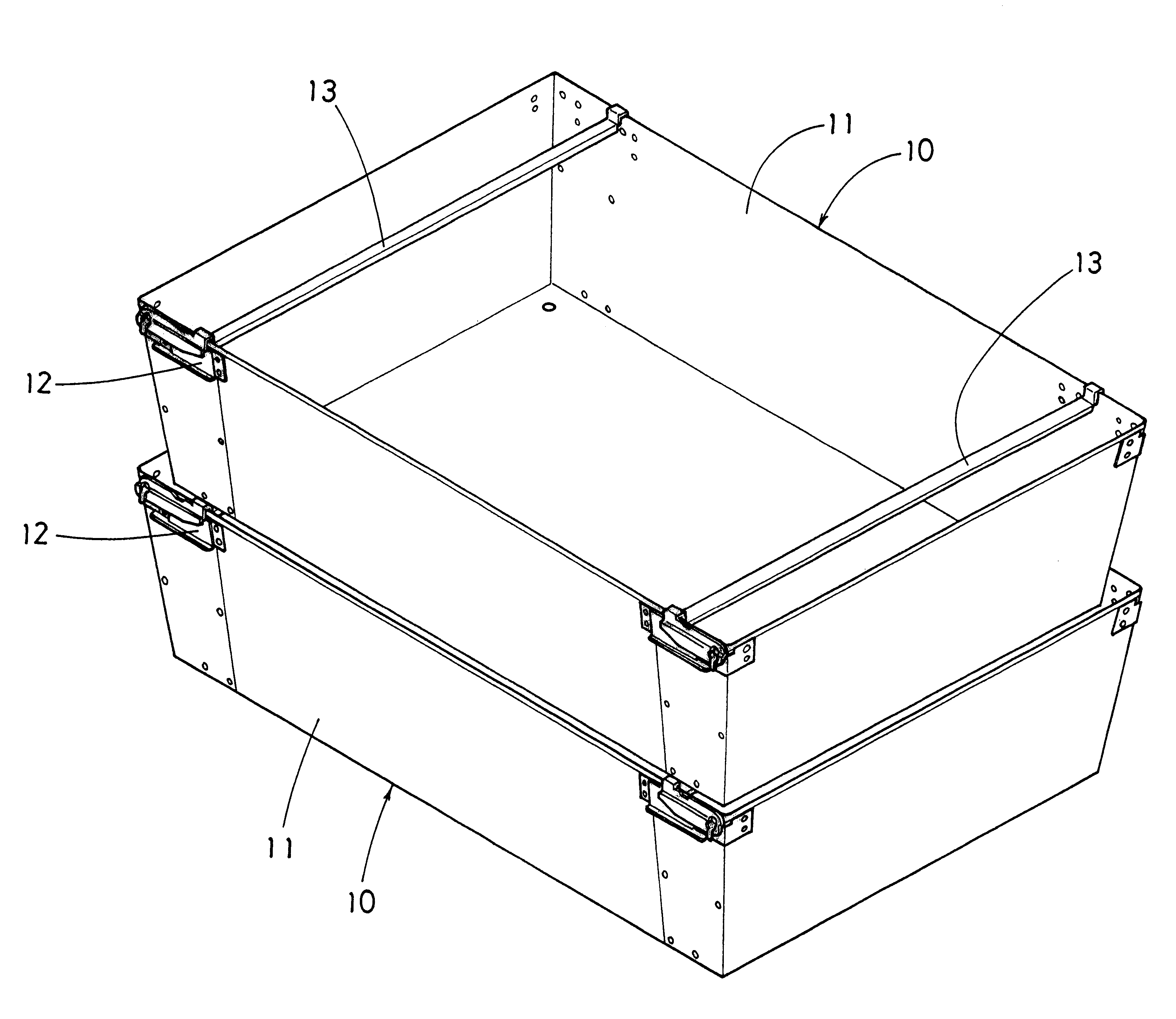
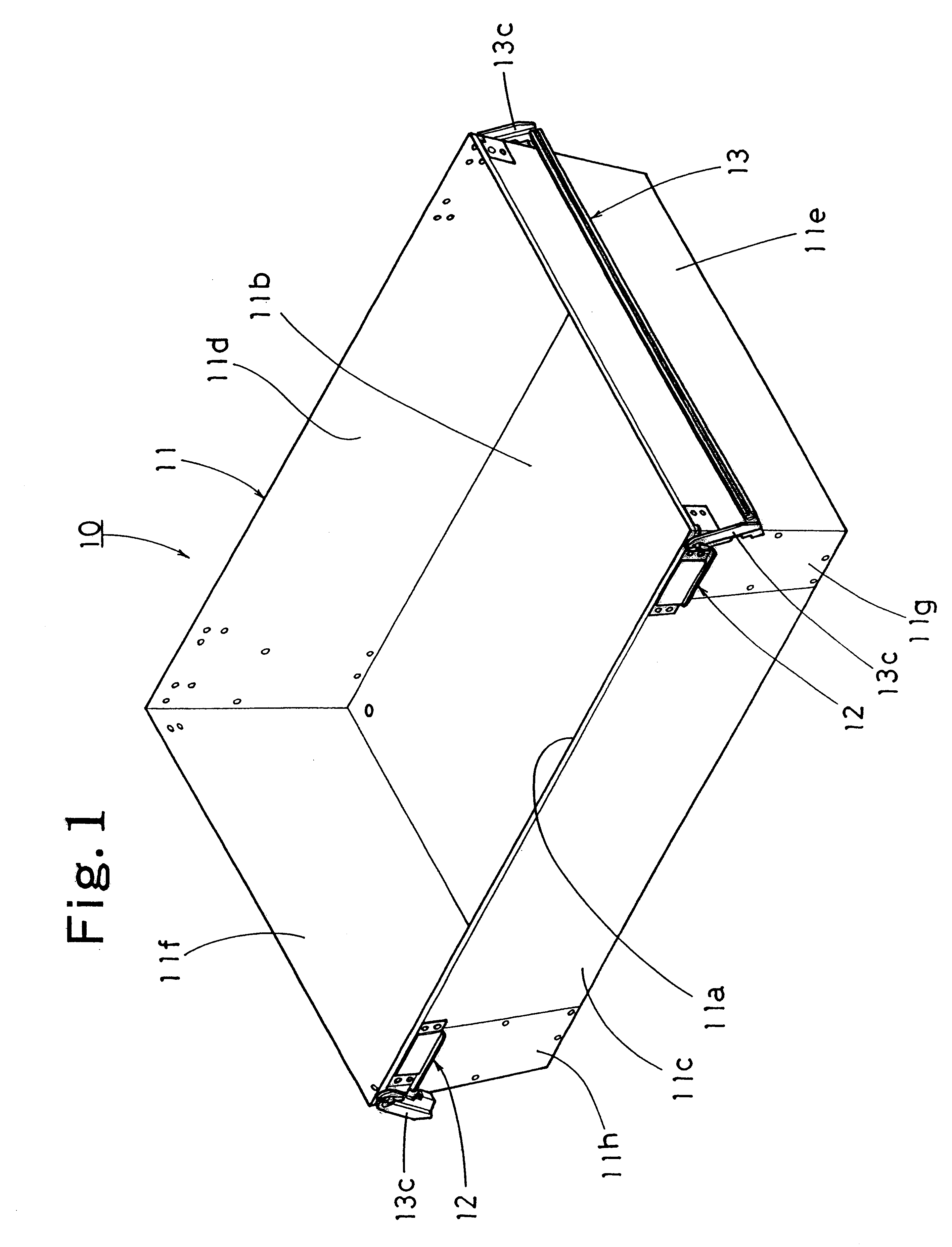
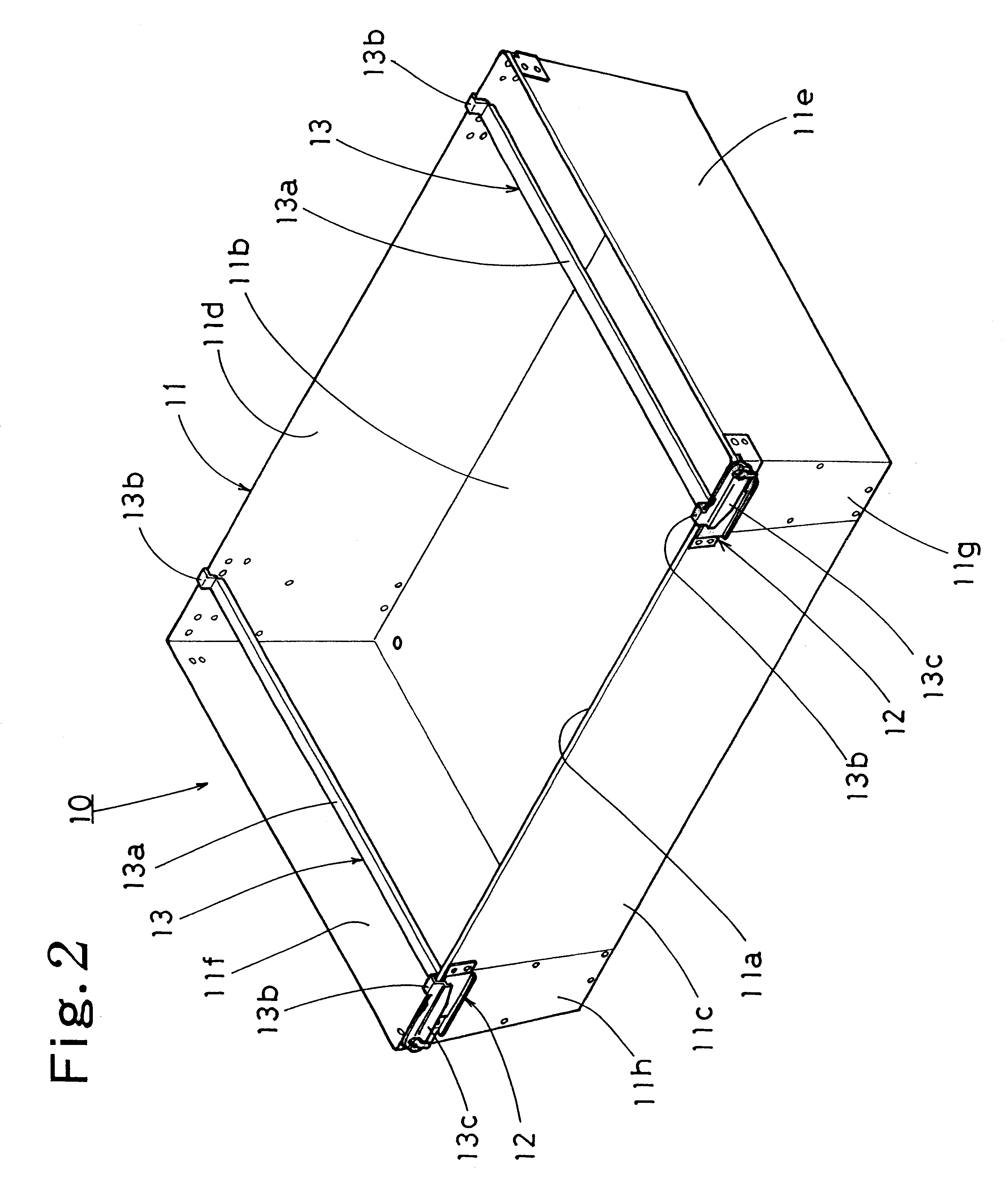
One embodiment of the present invention will be described with reference to the accompanying drawings. Referring to FIGS. 1 and 2, a transportation container 10 of the embodiment is shown. The container 10 comprises a generally box-shaped body made of a steel plate and a pair of handles 13 rotatably mounted on the body 11 by generally L-shaped brackets 12. The body 11 has a generally rectangular open upper end 11a, a bottom 11b and four side walls 11c to 11f. The side walls 11c to 11f are inclined downwardly inward so that a cross-sectional area of the body 11 is gradually decreased from the upper end to the bottom of the body 11. The side wall 11e has both ends formed with bent portions 11g respectively. The side wall 11f has both ends formed with bent portions 11h respectively. The bent portions 11g of the side wall 11e are welded to the side walls 11c and 11d respectively. The bent portions 11h of the side wall 11f are also welded to the side walls 11c and 11d respectively.

Each h...


PUM


Abstract

A transportation container includes a body having a plurality of side walls, a bottom and an open upper end, a pair of handles mounted on the body so as to be rotated inside or outside the body and including grip portions having both ends respectively, a pair of arms formed on the respective ends of each grip portion of each handle, and a pair of engaging portions formed on an interface between each grip portion and the corresponding arm. The side walls of the body are inclined downwardly inward so that a cross-sectional area of the body is gradually decreased from the upper end to the bottom of the body. Each arm has a distal end mounted on an outer face of one of the side walls of the body so that each handle is rotated inside or outside the body. Each engaging portion engages the upper end of the body, and each grip portion extends across the open upper end of the body and is located lower than an upper end of the side wall when each handle is rotated inside the body. Each engaging portion disengages from the upper end of the body and each grip portion being rotated outside the body when the handle is rotated outside the body.

Description

1. Field of the InventionThis invention relates to containers repeatedly used for transportation of products.2. Description of the Prior ArtThe prior art has provided a transportation container of the above-mentioned type made of plastic and having side walls inclined downwardly inward so that a cross-sectional area of a body is gradually decreased from an open upper end to a bottom of the body. When not used for the product transportation, a number of the containers are fitted into one another to be laid one upon another while prevented from becoming bulky.In use for the product transportation, products are accommodated into the container and a lid is then put onto the open upper end of the container. The containers are then laid one upon another. Since the lid and container are discrete from each other, the lid is prone to be lost. When the lid is lost, the container cannot be laid upon another during transportation.Furthermore, since the side walls of the prior-art container are ...

Claims


Application Information

Patent Timeline
Patent Type & Authority Patents(United States)
IPC IPC(8): B65D21/06B65D21/02
CPCB65D21/062
Inventor MORI, KIYOYOSHI
Owner TOYOTA TSUSHO
Why Eureka
Try Eureka