
Two-wheel hand truck

a two-wheeled, hand-held technology, applied in the direction of hand-held cart accessories, hand-held cart accessories, carriage/perambulator accessories, etc., can solve the problems of increasing the weight of the tare, requiring considerable structural expense, and affecting the handiness of the sack trolley

Inactive Publication Date: 2002-05-14
BIERMA JOCHUM
View PDF10 Cites 17 Cited by
  • Summary
  • Abstract
  • Description
  • Claims
  • Application Information

AI Technical Summary

Benefits of technology

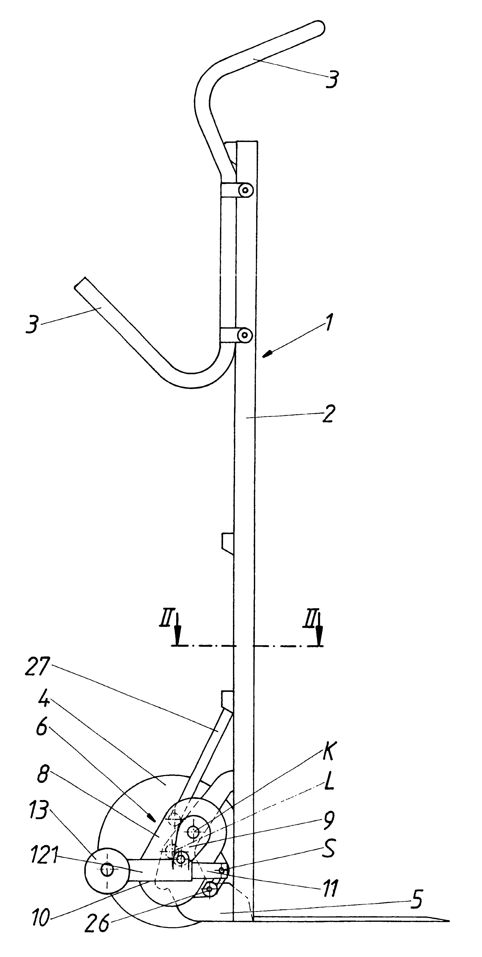
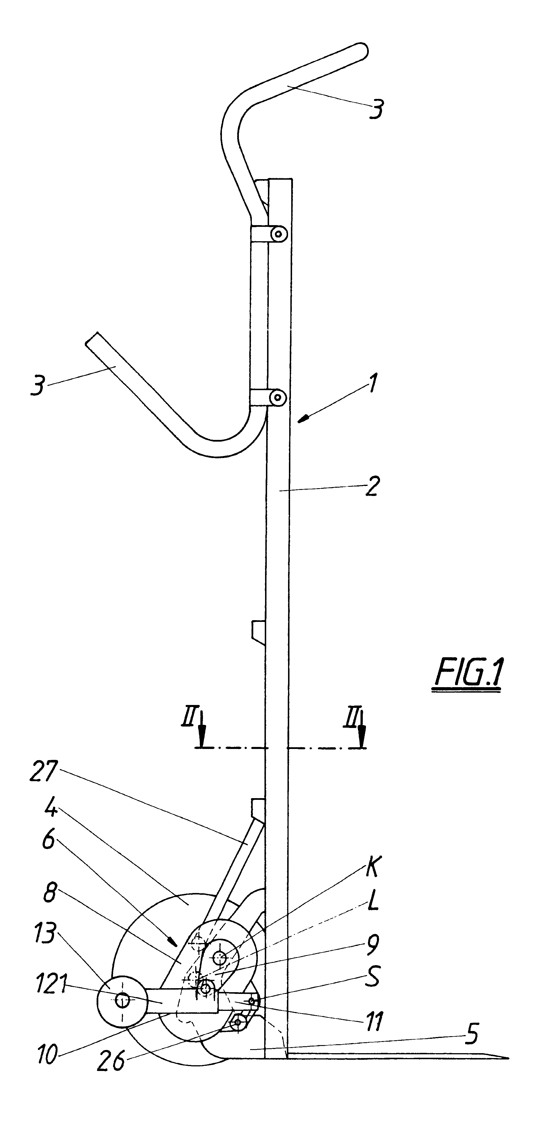
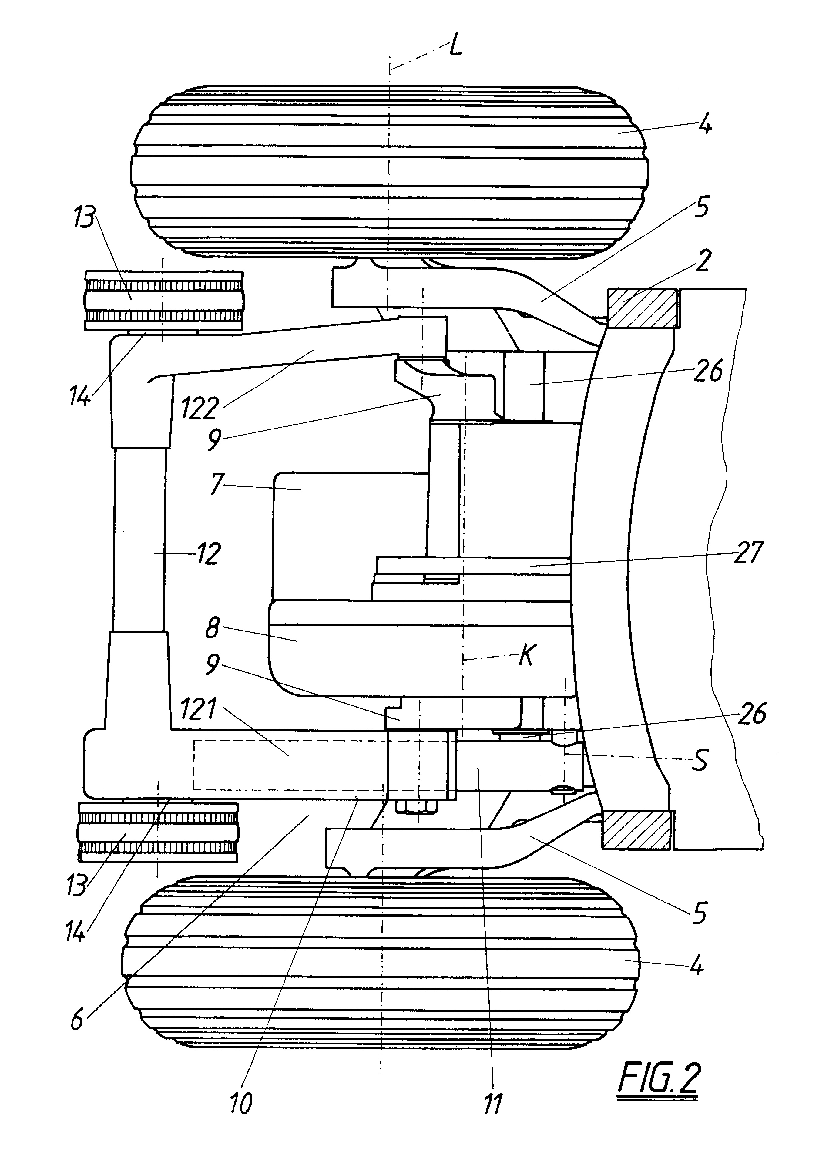
The invention solves this task in that the lifting arm is comprised of a swing guide component swivel-mounted about the swivel axis and a support component taking up the support rollers and longitudinally displaceable compared to the swivel guide component, whereby the crank drive is articulated on the support component with its crank arm. The free end of the support component is moved on the one hand by the superposition of the swivel movement of the swivel guide component effective thereon and the rotary movement of the crank arm on the other hand along an approximately reinform curved path, resulting in trouble-free climbing assistance according to the direction of movement with the support component and its support rollers. When the sack trolley is in a position corresponding to the travel position the support rollers of the support component are set engagingly on the next highest step tread for travelling up a step, are supported there and raise the trolley from one step to the other. On the contrary, during descent the support rollers remain supported on the respective upper step and the trolley is lowered by way of the lifting arm to the next lowest step, giving rise to a simple and functionally safe raising and lowering movement for automatic step travel. The lifting arm with the crank drive can be accommodated without difficulty in narrow spaces, for example between the carrying wheels of the sack trolley, and thereby alters the centre of gravity position of the sack trolley only insignificantly, in addition to which the hoist mechanism does not weigh excessively because of its simple structure and barely increases the tare weight of the trolley noticeably. The path of motion of the support rollers is influenced by appropriate adaptation of the crank throw, axle position, lifting arm length, articulation point of the crank throw on the support component and the like and is adapted to different step profiles, whereby the passage speeds of the path of the support rollers are adapted to the respective functional areas and the empty run and vertex areas are passed through more quickly than the lifting or lowering areas required for climbing steps.
It is particularly advantageous if the support rollers of the support component are equipped with a combined free-wheel and brake device which releases rotating of the support rollers in terms of the trolley travelling backwards, but which brakes counter-rotation of the support rollers. Release of the rotary movement of the support rollers in one direction and their braking instead of blocking in the counter-rotation direction facilitates climbing steps with the assistance of the hoist mechanism, since the position of the support rollers on the steps can be corrected effortlessly by the driver of the trolley without losing the necessary support effect of the support rollers.

Problems solved by technology

This hoist mechanism thus requires considerable structural expense and is also associated with a corresponding space requirement which impairs the handiness of the sack trolley and undesirably increases its tare weight.
Further to this, because the centre of gravity is misplaced upwards due to the hoist mechanism there is less stable handling of the trolley as it climbs steps, and not least of all in tricky situations the result is unsafe climbing assistance adapted minimally to the step profiles of the step due to the stilt movements of the support wheels.

Method used


Image

  • Two-wheel hand truck
  • Two-wheel hand truck
  • Two-wheel hand truck

Examples


Embodiment Construction

The object of the invention is therefore to create a sack trolley of the type mentioned at the outset, which is distinguished by its easily handled and functional hoist mechanism with a simple and compact structure.

The invention solves this task in that the lifting arm is comprised of a swing guide component swivel-mounted about the swivel axis and a support component taking up the support rollers and longitudinally displaceable compared to the swivel guide component, whereby the crank drive is articulated on the support component with its crank arm. The free end of the support component is moved on the one hand by the superposition of the swivel movement of the swivel guide component effective thereon and the rotary movement of the crank arm on the other hand along an approximately reinform curved path, resulting in trouble-free climbing assistance according to the direction of movement with the support component and its support rollers. When the sack trolley is in a position corre...


PUM


Abstract

A sack trolley (1) comprises a support frame (2) presenting a lower pair of carrying wheels (4) and a hoist mechanism (6) for climbing steps, which comprises a lifting arm (10) equipped with support rollers at its free end and which can be swivelled about a swivelling axis (S) parallel to the carrying wheel axis (L) by means of a crank drive (8). In order to achieve step-climbing assistance which is simple, space-saving, easy to handle and functionally safe, the lifting arm (10) is comprised of a swing guide component (11) swivel-mounted about the swivel axis (S) and a support component (12) taking up the support rollers (13) and longitudinally displaceable compared to the swivel guide component (11), whereby the crank drive (8) is articulated on the support component (12) with its crank arm (9).

Description

The present invention relates to a sack trolley having a support frame presenting a lower pair of carrying wheels and upper handles and a hoist mechanism for climbing steps, which comprises a lifting arm equipped with return rollers at its free end and which can be swivelled about a swivelling axis parallel to the carrying wheel axis by means of a crank drive.PRIOR ARTA similar sack trolley is disclosed in EP 0 533 650 B and its hoist mechanism for climbing steps has thoroughly proven itself, whereby the lifting arm designated as support frame engages in a crank guide solid with the support frame by way of a guide member in its longitudinal central region, and its end averted from the free end with the return roller is articulated on the crank arm of the crank drive. Because of the cooperation of support frame, crank drive and crank guide the support wheels describe a stilt movement reaching forwards or backwards with switching on, off and reversing of the drive motor, by means of w...

Claims


Application Information

Patent Timeline
IPC IPC(8): B62B5/02
CPCB62B5/023
Inventor BIERMA, JOCHUM
Owner BIERMA JOCHUM
Learn More