Directional seat valve

a seat valve and directional technology, applied in the direction of valve details, instruments, fluid pressure control, etc., to achieve the effect of reducing process-technological and assembly-technological expenditures

Inactive Publication Date: 2002-05-21
HYDRAULIK RING
View PDF3 Cites 9 Cited by
  • Summary
  • Abstract
  • Description
  • Claims
  • Application Information

AI Technical Summary

Benefits of technology

It is therefore an object of the present invention to provide a directional seat valve and a method for assembling the directional sea

Problems solved by technology

The problem with such directional seat valves is that the magnetic operating point of the solenoid must be adjusted relatively precis

Method used


Image

  • Directional seat valve
  • Directional seat valve
  • Directional seat valve

Examples


Embodiment Construction

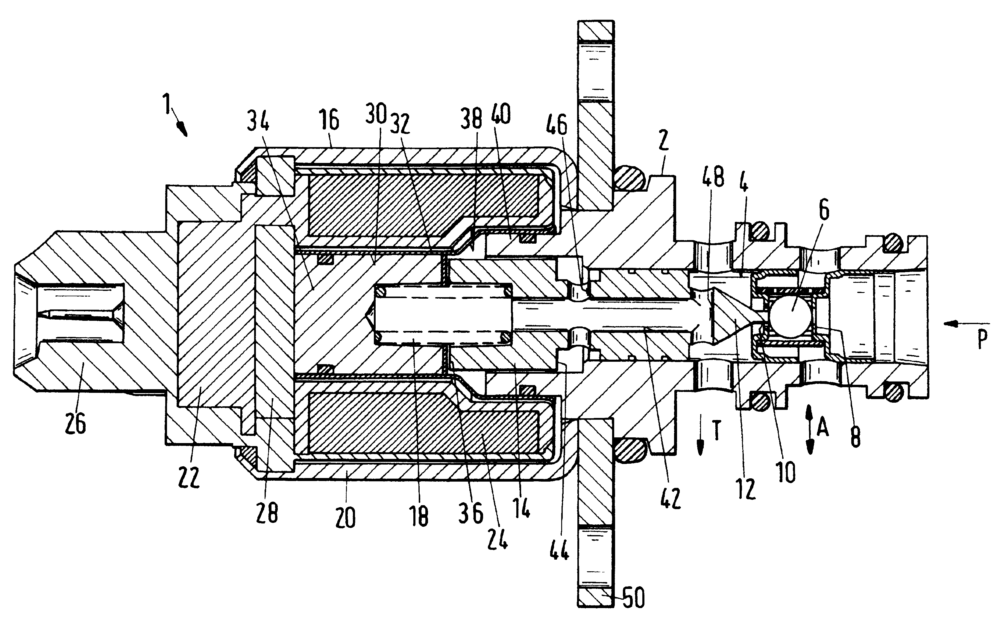
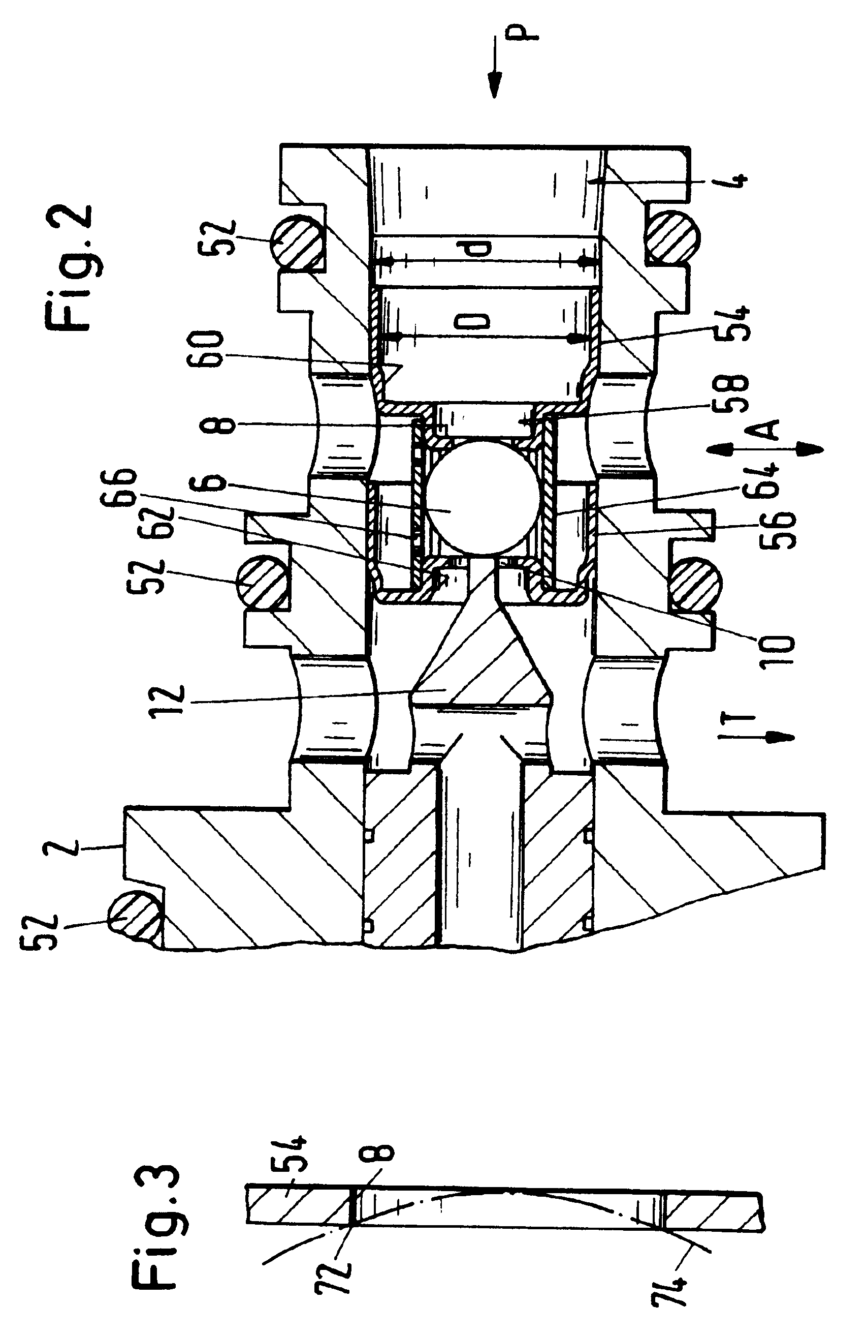
FIG. 1 shows a section of a directly controlled 3 / 2 directional seat valve 1 (the designation 3 / 2 refers to the number of connectors available, i.e., three, and the number of connectors, i.e., two, to be respectively connected for operation). It has a cartridge configuration with a valve housing 2 having a valve bore 4 into which a pressure connector P, a working connector A, and a tank connector T open. The pressure connector P opens axially into the valve bore 4, while the two connectors A and T are embodied as radial star bores. The 3 / 2 directional seat valve 1 is a so-called single ball valve and has a valve body 6 correlated with two valve seats 8, 10. These valve seats 8, 10 will be described in more detail at a later point.

The base position represented in FIG. 1 shows the valve body 6 being pushed by a push rod 12 against the valve seat 8 to the right in FIG. 1. This push rod 12 is a unitary (monolithic) part of the armature 14 of a solenoid 16 and is biased by a pressure spr...


PUM


Abstract

A directional seat valve has a valve housing having a pressure connector for supplying pressure medium to the valve housing, a tank connector for returning pressure medium to a pressure medium tank, and a working connector for supplying pressure medium to a working device. The valve housing has a valve bore. Shaped parts with a valve seat are press-fit into the valve bore. A valve body in the valve bore controls together with the valve seats the pressure medium flow between the connectors. The seat valve is assembled by press-fitting the first shaped part with its valve seat into the valve bore, inserting the valve body into the valve bore, and press-fitting the second shaped part with its valve seat into the valve bore. The press-fit insertion depth of the first and second shaped parts in the valve bore is selected based on the position of the armature push rod.

Description

BACKGROUND OF THE INVENTION1. Field of the InventionThe invention relates to a directional seat valve comprising a valve body which is arranged in a valve bore and biased against at least one valve seat. It is lifted off the valve seat for connecting a pressure connector to a tank connector or a work connector. The invention furthermore relates to a method for assembling such a directional seat valve.2. Description of the Related ArtSuch directional seat valves have a valve housing with an axial bore in which a valve body is moveably arranged. The valve body is biased by a pressure spring against the valve seat. Upon surpassing a predetermined pressure at the inlet connector, the valve body is lifted off the valve seat and moved into an opening position in which the inlet connector is connected to an outlet connector, for example, a work connector or a tank connector.In the publication "Der Hydraulik Trainer", vol. 1, Mannesmann Rexrodt GmbH, 1991, p. 203, a directional seat valve i...

Claims


Application Information

Patent Timeline
IPC IPC(8): F15B13/04F15B13/00F16K11/044F16K31/06
CPCG05D16/2013F15B13/0405G05D16/2024Y10T137/86622Y10T137/0502
Inventor ZAPF, FRIEDRICH
Owner HYDRAULIK RING
Why Eureka
Try Eureka