Nail gun with safety portion mechanism for preventing misfires

a safety portion and nail gun technology, applied in the field of nail guns, can solve the problems of difficult to see the nail tip, difficult to lengthen the stroke of the workpiece contact member, and the inability to adjust the initial lever within the movement range of the trigger, etc., and achieve the effect of accurate setting and reliable operation

Inactive Publication Date: 2002-05-28
KOKI HLDG CO LTD
View PDF8 Cites 48 Cited by
  • Summary
  • Abstract
  • Description
  • Claims
  • Application Information

AI Technical Summary

Benefits of technology

It is an objective of the present invention to overcome the above-described problems and provide a nail gun that more easily allows visual confirmation of the nail tip location and that uses a simpler configuration, which improves reliability by helping prevent the danger of misfires.
With this configuration, a long stroke can be achieved for the safety portion. Therefore, the lower end of the safety portion can be separated from the nail tip in the initial condition, so that whether the nail tip is properly set in the clasp hole can be visually confirmed with ease. That is, the position where nails will be driven into the work piece can be accurately set.
Also, only the trigger arm is provided within the trigger and the safety portion is configured from only the upper safety portion and the lower safety portion. Operations are more reliable because the configuration is so simple.
As a result, a nail driving operation can be reliably performed.

Problems solved by technology

However, the intermediate lever can only be lengthened within the movement range of the trigger.
Therefore, it is difficult to lengthen the stroke of the work-piece contact member.
This makes it difficult to see the nail tip so that it is difficult to position the nail at the precise position where it is to be driven into the work piece.
Also, the intermediate lever and the operation lever are provided in a narrow space above the trigger and operate in a fairly complicated manner against urging force of springs.
A slight error in component or position dimensions, abrasion caused by friction, or dust, dirt, and the like clinging to components could easily become the cause of misfires.
As a result, reliability of the nail gun suffers.

Method used


Image

  • Nail gun with safety portion mechanism for preventing misfires
  • Nail gun with safety portion mechanism for preventing misfires
  • Nail gun with safety portion mechanism for preventing misfires

Examples


Embodiment Construction

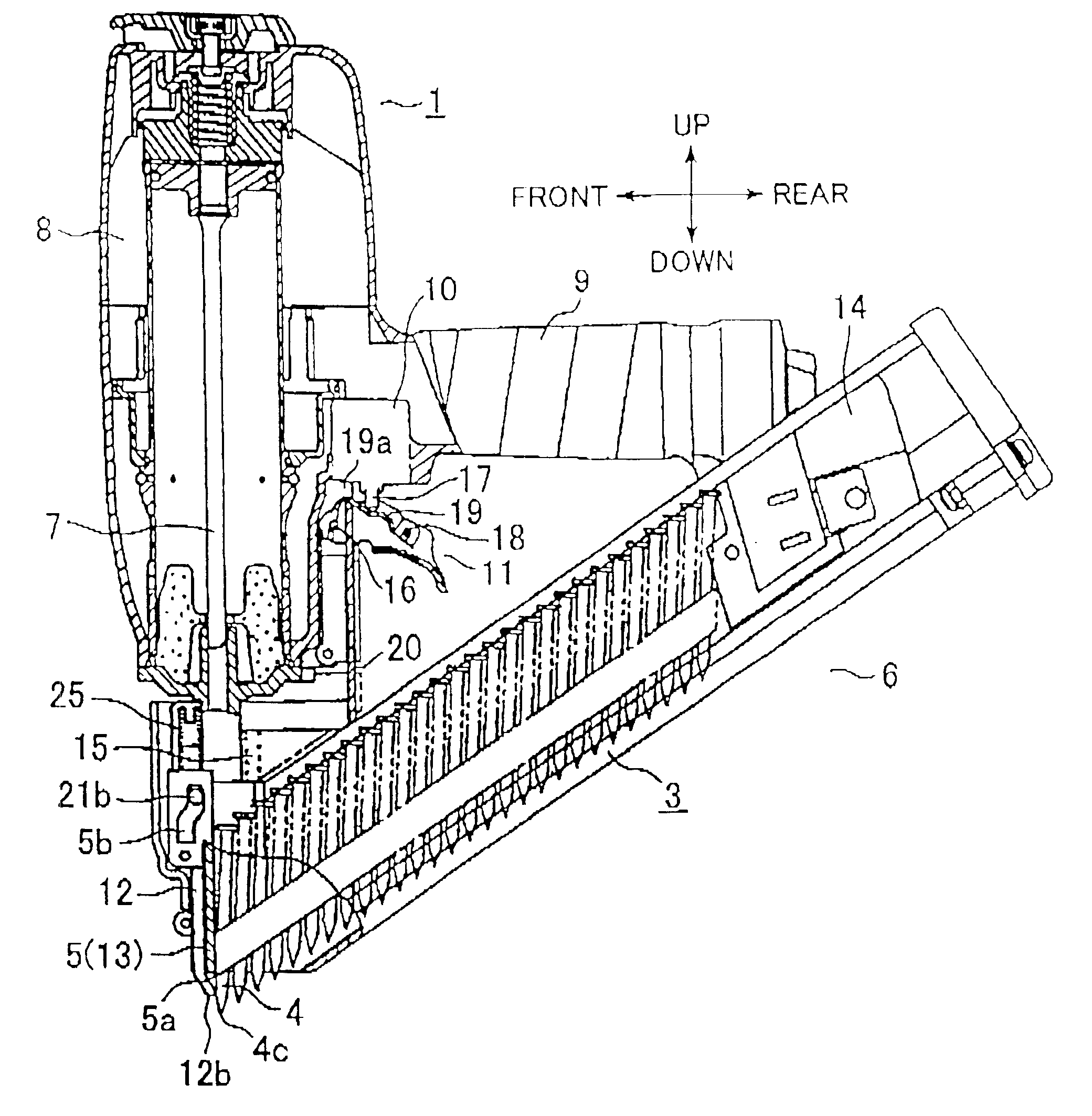
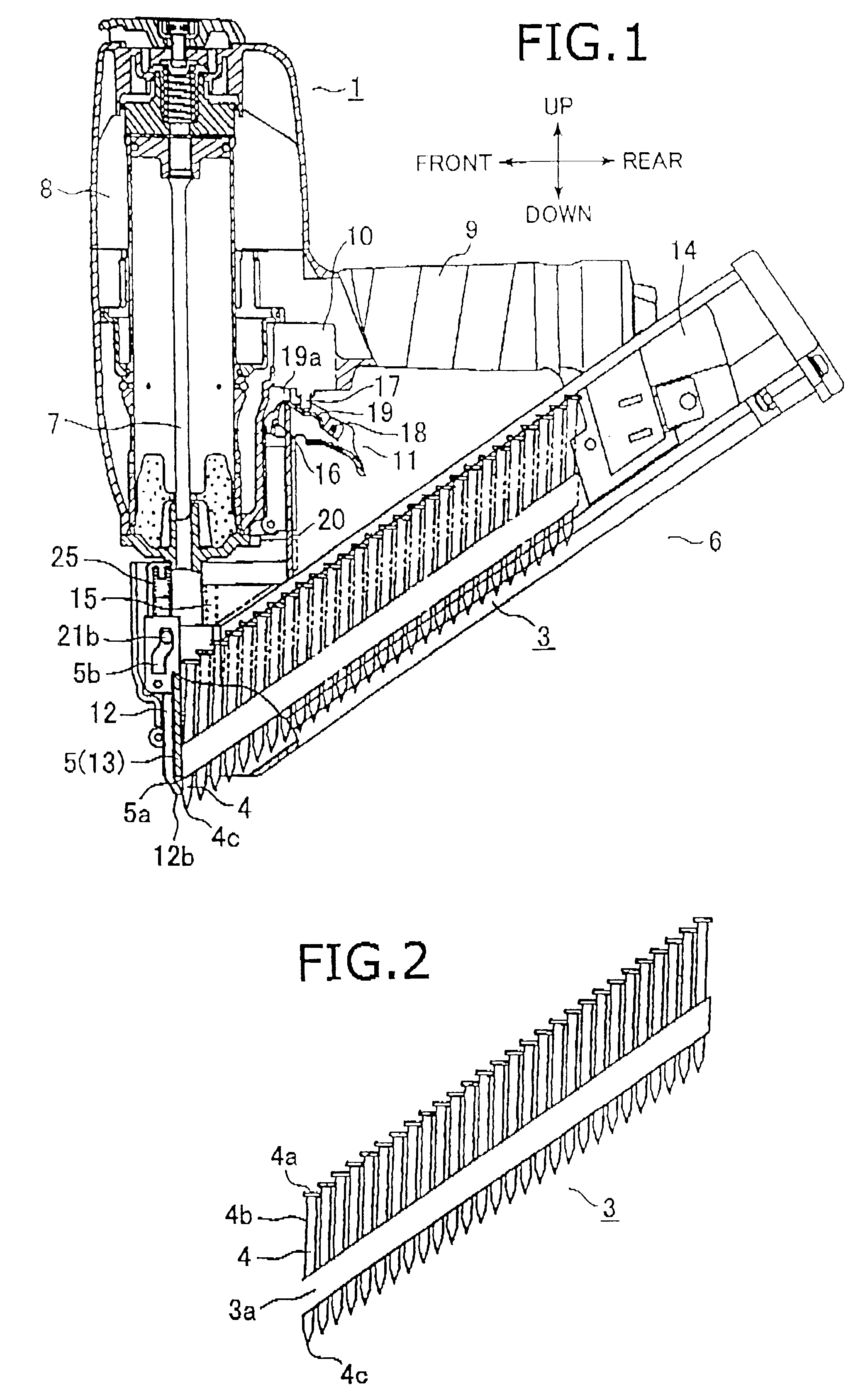
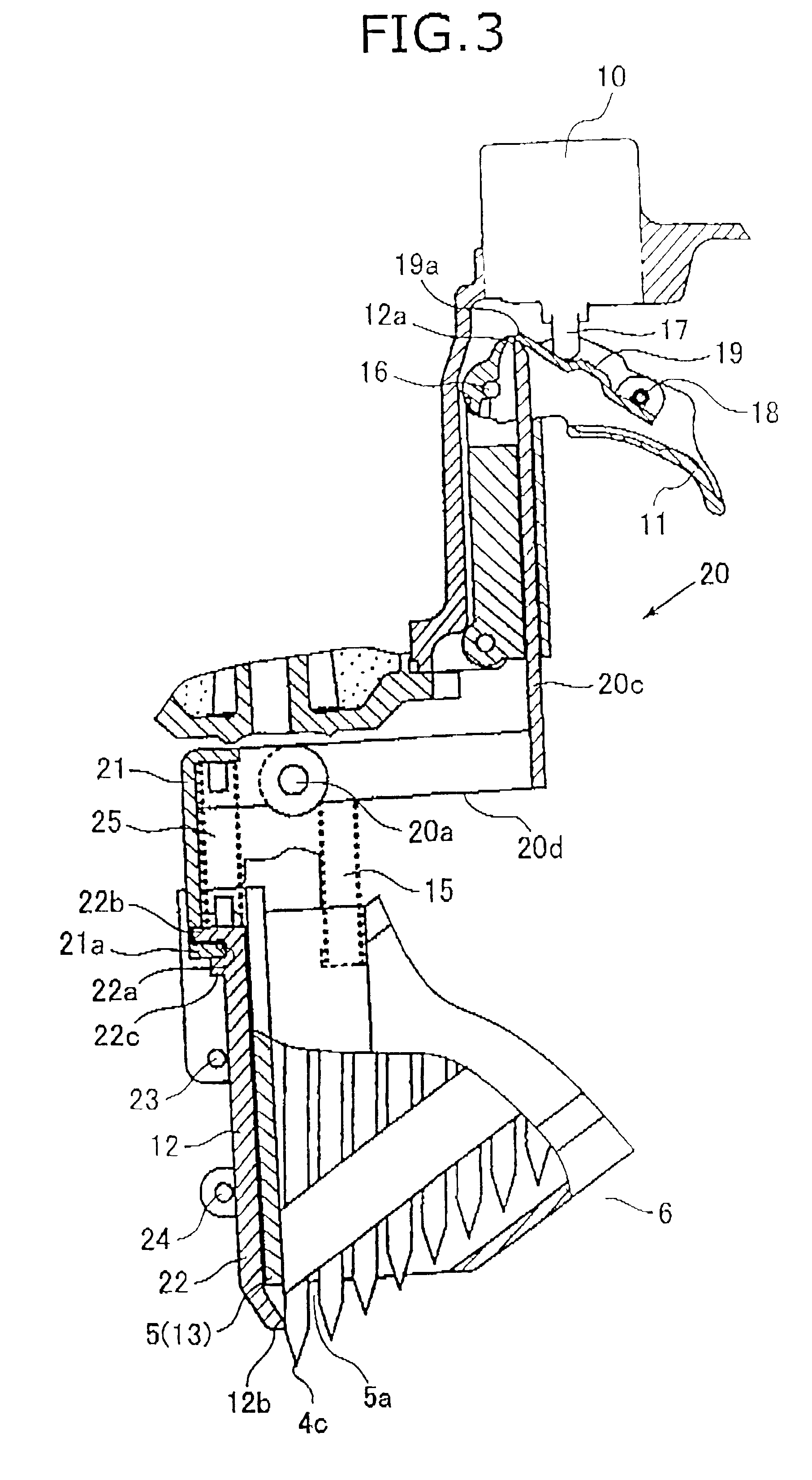
Next, a nail gun according to a first embodiment of the present invention will be provided while referring to FIGS. 1 to 13. To facilitate explanation, the directional terms up, down, front, and rear will be used referring to orientation in which the nail gun is intended to be used and as indicated in FIG. 1.

As shown in FIG. 1, a nail gun 1 includes a nail ejection portion 5, a magazine 6, a drive portion 8, a trigger 11, and a safety portion 12. The magazine 6 houses connected nails 3 that are supplied to the nail ejection portion 5. As shown in FIG. 2, the connected nails 3 are arranged on a single plane, separated by a fixed distance, and connected by a connection band 3a. Each nail 4 typically has a circular head 4a at its upper end, a cylindrical body 4b, and an acutely pointed tip 4c. As shown in FIG. 1, the magazine 6 includes a feeder 14 and a feeder spring (not shown). The feeder 14 receives pressure from the feeder spring and feeds the nails 4 to the nail ejection portion ...


PUM

PropertyMeasurementUnit
urging forceaaaaaaaaaa
timeaaaaaaaaaa
lengthaaaaaaaaaa

Abstract

A nail gun has a free end 19a and central potion of a trigger arm 19 positioned within a trigger 11, on an upper end 12a of a safety portion 12 and at a plunger 17, respectively. When the trigger 11 is pivoted on its pivot end 16, pivoting movement of the trigger 11 moves a pivot end 18 of the trigger arm 19 to press the central portion of the trigger arm 19 into contact with the plunger 17 and, with the plunger 17 serving as a fulcrum, to press the free end 19a downward against the upper end 12a of the safety portion 12. If downward movement of the safety portion 12 is obstructed when the trigger 11 is pivoted, the upper end 12a contacted by the free end 19a of the trigger arm 19 serves as a fulcrum around which the trigger arm 19 pivots with movement of the trigger 11, whereupon the central portion of the trigger arm 19 presses the plunger 17 inward so that an activation switch 10 activates a blade 7 to eject a nail through a nose piece 5.

Description

1. Field of the InventionThe present invention relates to a nail gun that drives a nail through, for example, the hole of a connection clasp and to a nail gun that can accurately drive nails into a desired drive position.2. Description of the Related ArtA variety of different types of clasp fixing nail guns have been proposed. U.S. Pat. No. 5,193,730 discloses a nail gun that separates nails one at a time from a nail band and supplies the nail to a nail injection hole of the nosepiece. The nail tip is protruded from the end of the nosepiece before the nail gun drives the nail.The nail gun further has a safety mechanism with a work-piece contact member, an intermediate lever, and an operation lever. The work-piece contact member extends from the nose of the nail gun to the base of the intermediate lever. When the trigger of the nail gun is pressed, the operation lever moves toward or away from an activation plunger, depending on the position of the work-piece contact member and the i...

Claims


Application Information

Patent Timeline
Patent Type & Authority Patents(United States)
IPC IPC(8): B25C1/00B25C1/04B25C7/00
CPCB25C1/008
Inventor AKIBA, YOSHITAKA
Owner KOKI HLDG CO LTD
Why Eureka
Try Eureka