Seat belt tightener

a seat belt and belt technology, applied in the direction of process and machine control, instruments, pedestrian/occupant safety arrangements, etc., can solve problems such as pulling forces

Inactive Publication Date: 2002-05-28
KEY SAFETY SYST
View PDF19 Cites 72 Cited by
  • Summary
  • Abstract
  • Description
  • Claims
  • Application Information

AI Technical Summary

Problems solved by technology

This should result in pulling forces passing into a seat belt by an electromotive tightening drive prior to the actual crash.

Method used


Image

  • Seat belt tightener
  • Seat belt tightener
  • Seat belt tightener

Examples


Embodiment Construction

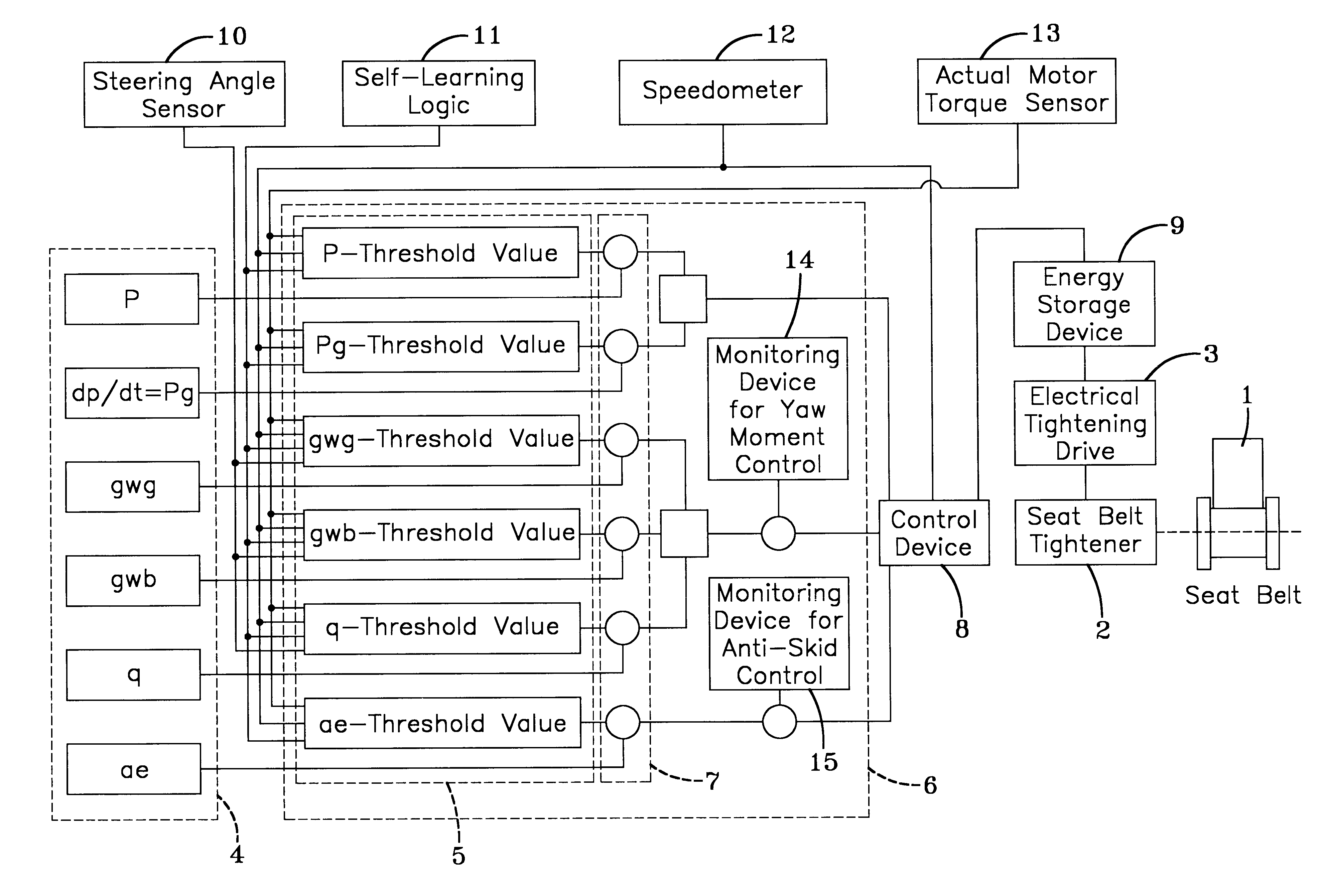
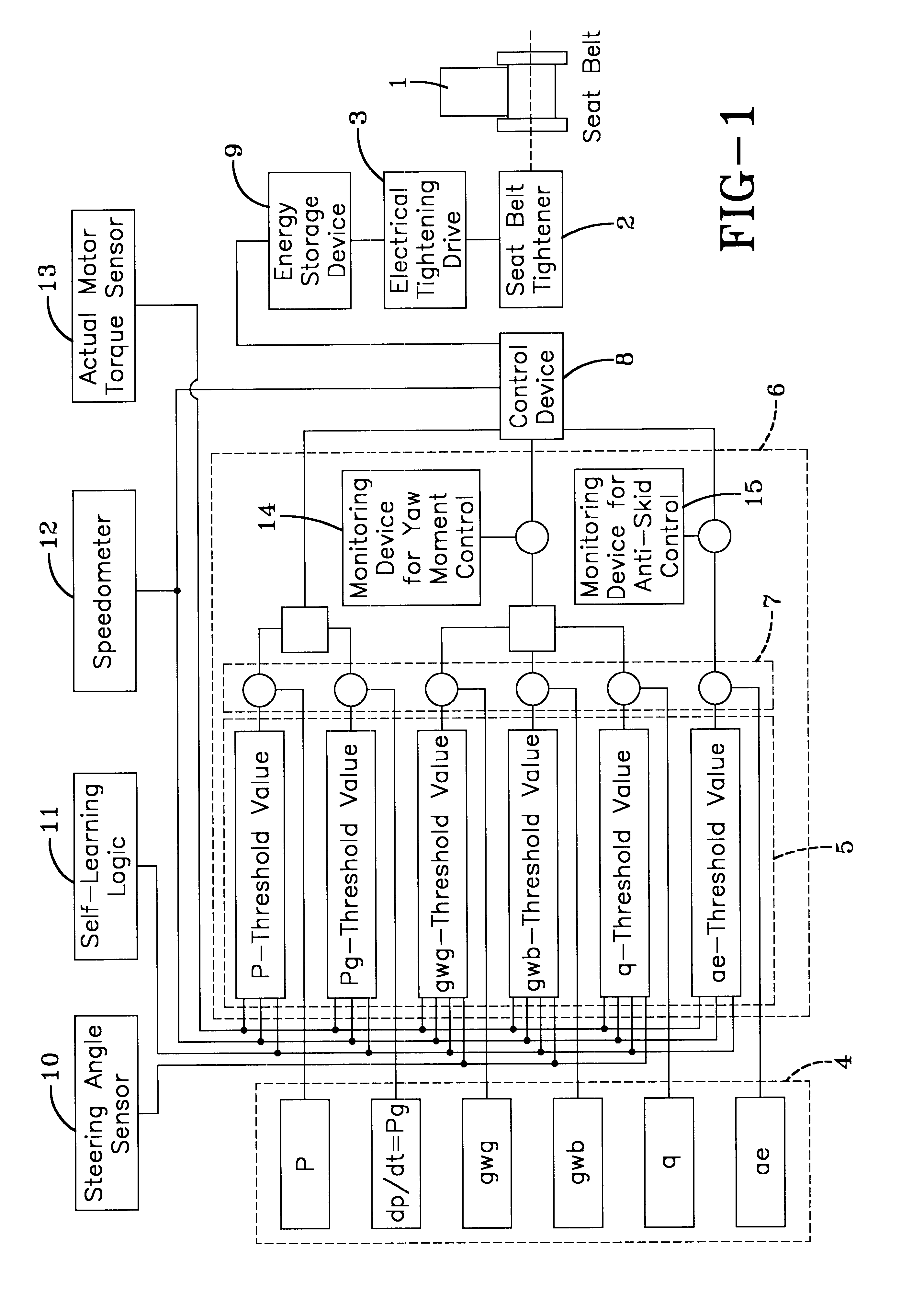
The embodiment of the vehicle occupant restraint device according to the invention shown schematically in FIG. 1 comprises a seat belt 1 that is configured in a known manner as a three-point seat belt. In addition, the represented vehicle occupant restraint device comprises a seat belt tightener 2 that includes an electrical tightening drive 3. The electrical tightening drive can be an electric motor. An energy storage device 9 supplies energy to the electrical tightening drive 3. The activation of the electrical tightening drive occurs in dependence on the output signals of a control device 8. The control device receives the output of an evaluating device 6 that assesses indicating signals that are generated by various sensors of an array of sensors 4. The electrical indicating signals generated by the array of sensors 4 are proportional to the respective vehicle dynamic driving conditions, which are detected or measured by the various sensors of the array of sensors during the ope...


PUM


Abstract

A seat belt tightener has an electrical tightening drive that can be operated in dependence on sensor signals of sensors assessed in an evaluating device. The sensors detect specific vehicle dynamic conditions and transmit electrical indicating signals that are proportional to the detected condition to the evaluating device. The evaluation device compares the signals with allocated threshold values to determine whether or not a potential crash situation is present. Should a potential crash situation be present, the electrical tightening drive is controlled accordingly.

Description

The present invention relates to a seat belt tightener having an electrical tightening drive.DISCUSSION OF PRIOR ARTDE 195 20 721 A1 teaches a vehicle occupant restraint device with an information system, for instance a pre-crash sensor, used to anticipate a crash prior to any deformation occurring to the motor vehicle and to emit a corresponding signal. This should result in pulling forces passing into a seat belt by an electromotive tightening drive prior to the actual crash. The length of the seat belt extracted can be measured by a sensor to generate an optimal pulling force for tightening the seat belt. This enables the vehicle occupant to already be placed in an optimal position preceding an actual crash, for instance during emergency braking. The known vehicle occupant restraint system evaluates signals that are detected by pre-crash sensors immediately before a crash.EP 0893313 A2 teaches a vehicle occupant restraint device with a seat belt which, with the help of an electro...

Claims


Application Information

Patent Timeline
Patent Type & Authority Patents(United States)
IPC IPC(8): B60R21/01B60R22/46B60R21/013
CPCB60R21/013B60R2022/4666B60R2021/01313B60R2021/01311
Inventor SPECHT, MARTIN
Owner KEY SAFETY SYST
Why Eureka
Try Eureka