Destructible locking device

a locking device and destructible technology, applied in the direction of identification means, screws, instruments, etc., can solve the problems of destructible disassembly of the locking device by any tool capable of exerting the required compressive force, cumbersome operation cycles, and heavy tools carried by utility personnel,

Inactive Publication Date: 2002-06-18
INNER TITE A DIV OF YARA ENG
View PDF27 Cites 72 Cited by
  • Summary
  • Abstract
  • Description
  • Claims
  • Application Information

AI Technical Summary

Problems solved by technology

One drawback with this type of lock is that it may be destructively disassembled by any tool capable of exerting the required compressive force.
This in turn requires utility personnel to carry tools that are heavy, cumbersome, and have unduly long ope

Method used


Image

  • Destructible locking device
  • Destructible locking device
  • Destructible locking device

Examples


Embodiment Construction

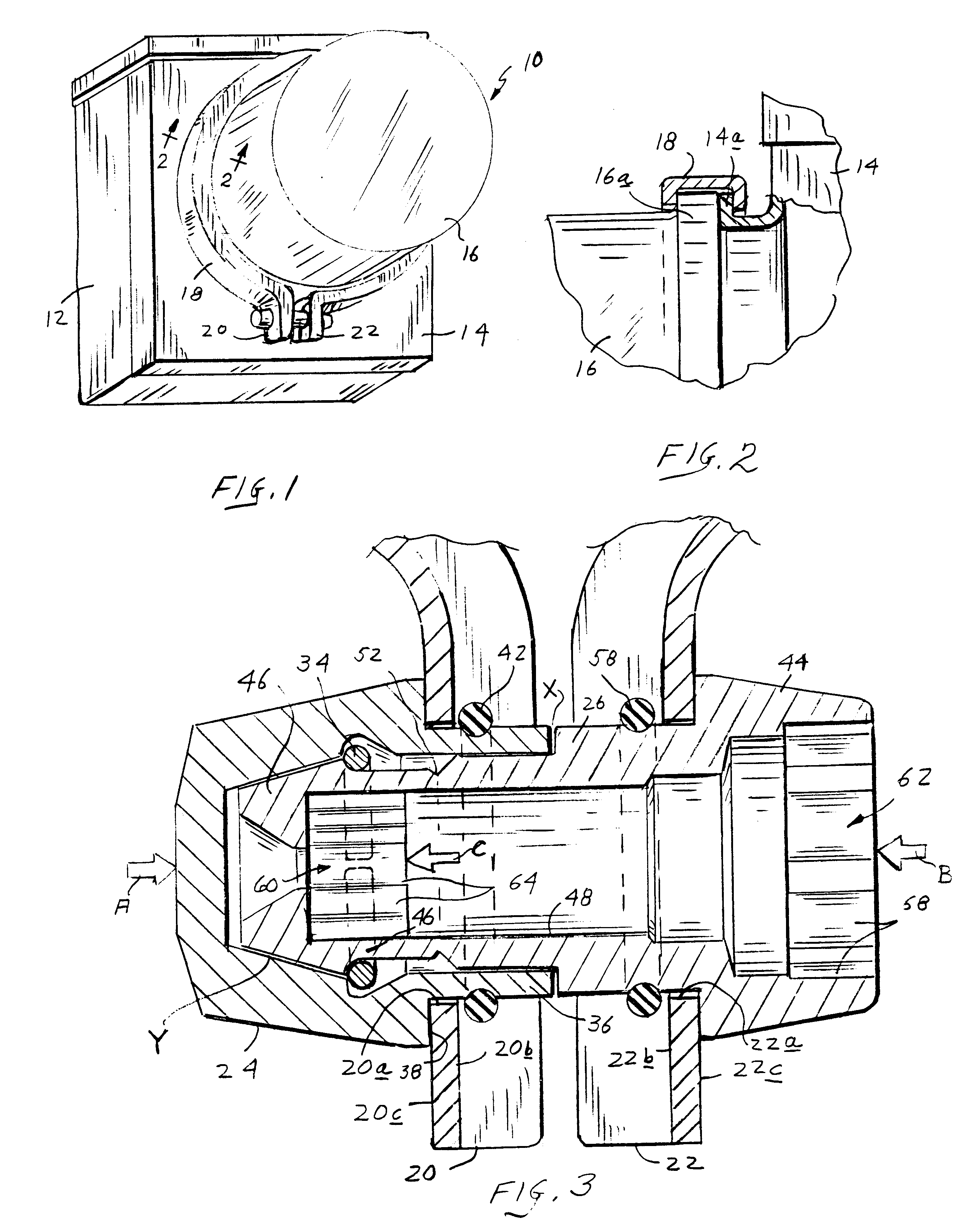
With reference initially to FIGS. 1 and 2, a conventional utility meter is shown at 10 comprising a meter box 12 closed by a cover 14 which supports a transparent dome 16 enclosing the meter mechanism (not shown). The cover 14 and dome 16 have circular flanges 14a, 16a which are secured in a confronting abutting relationship by a channel shaped split retaining ring 18 The ends of the ring are bent outwardly to provide first and second mating components 20, 22.

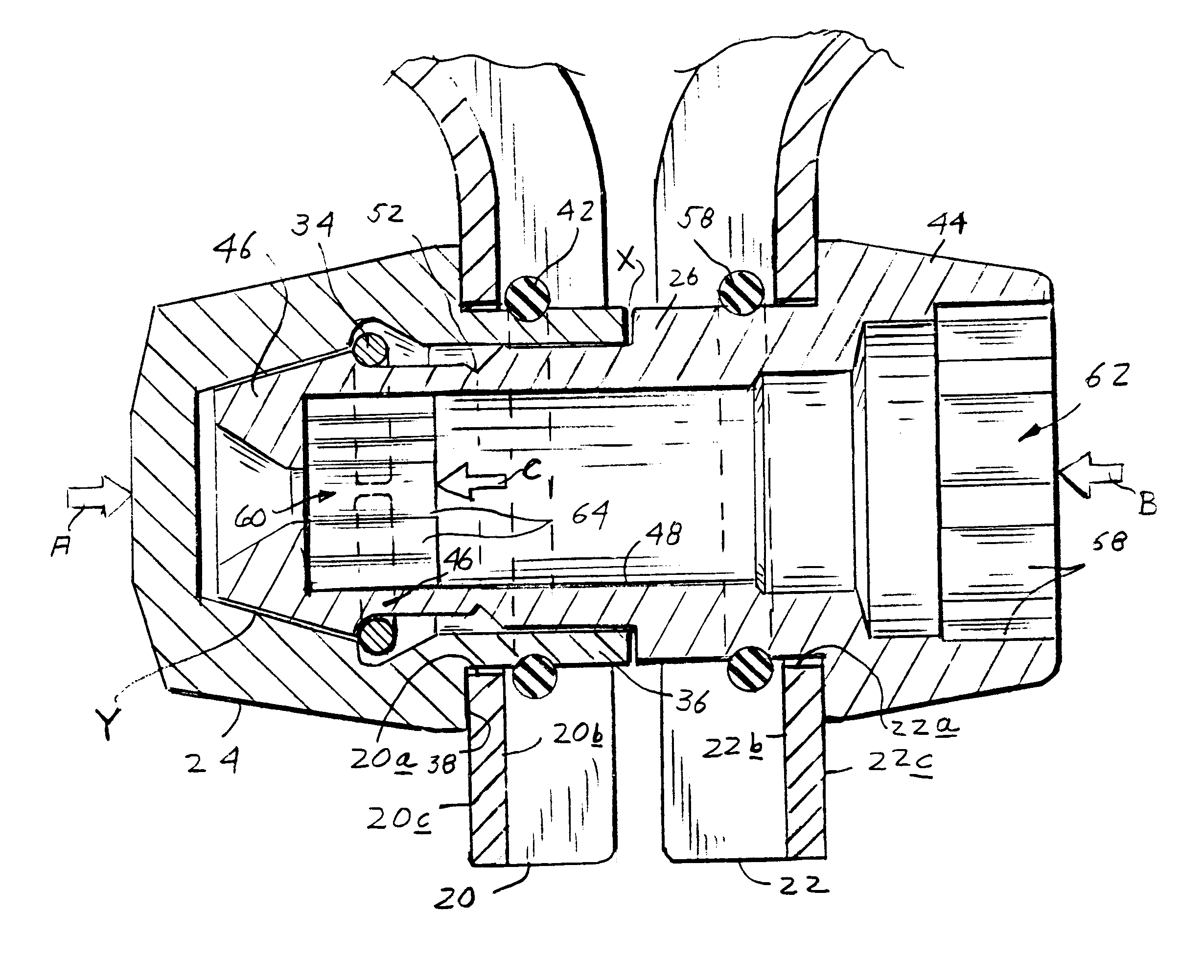
As can best be seen by further reference to FIG. 3, the mating components 20, 22 are provided respectively with first and second openings 20a, 22a extending between inner and outer surfaces 20b, 20c and 22b, 22c.

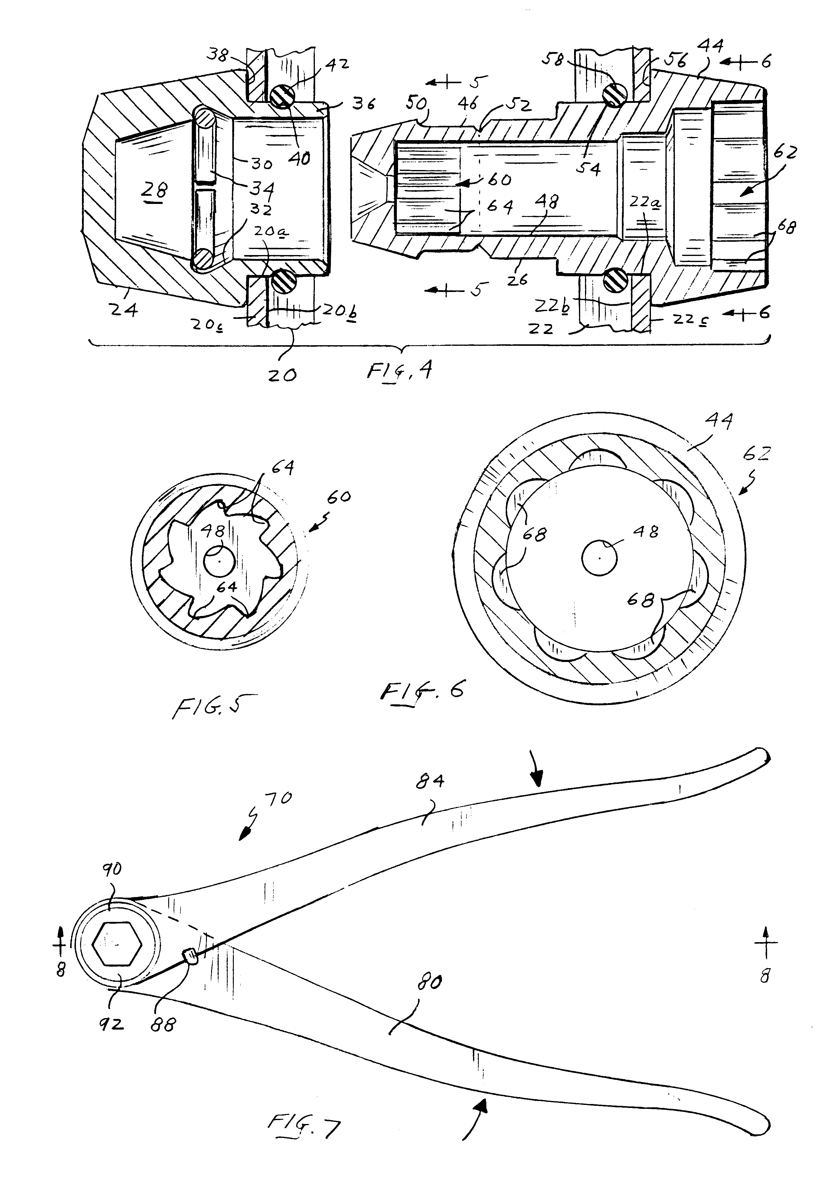
One embodiment of a locking device in accordance with the present invention comprises a receiving element in the form of a hollow cap 24 and a pin 26. With additional reference to FIGS. 4-6, it will be seen that the cap 24 has an interior chamber 28 accessible via an open mouth 30. An interior groove 32 contains a resil...


PUM


Abstract

A locking device is disclosed for interlocking two members having aligned openings extending therethrough. The device includes a hollow cap and a pin with an enlarged head at one end and a nose at the opposite end. The pin is insertable through the aligned openings of the members, with its nose received in interlocked engagement within the cap, and with the two members captured between the cap and the enlarged head of the pin. A frangible portion of the pin is severable in response to relative rotation between its nose and enlarged head to thereby destructively disassemble the locking device.

Description

1. Field of the InventionThis invention relates to destructible locking devices of the type employed to releasably interconnect mating components of security devices. Such security devices are widely employed by public utilities to secure meters, supply valves, etc. against unauthorized access.2. Description of the Prior ArtThe operating mechanism of a conventional utility meter is typically enclosed within a transparent dome which in turn is removably attached to the cover of a box-shaped housing. The cover and dome have circular rims that are held in an axially aligned abutting relationship by a channel-shaped split retaining ring. The ends of the retaining ring are configured as mating components which are releasably interconnected in a confronting relationship by locks of varying design.One such lock of the destructible type is disclosed in U.S. Pat. No. 5,161,838 (Ely et al.), where the mating end components of the split retaining ring are captured between an enlarged head at o...

Claims


Application Information

Patent Timeline
IPC IPC(8): E05B65/00F16B19/04F16B21/00F16B21/06F16B19/08G09F3/03E05B39/00E05B39/02F16B21/18
CPCE05B65/0089G09F3/0364F16B21/065F16B19/08E05B39/02F16B21/18Y10T292/205Y10T292/214Y10T292/51
Inventor MAHANEY, JOHN
Owner INNER TITE A DIV OF YARA ENG
Why Eureka
Try Eureka