Swivel draw bar structure of a suitcase

a draw bar and suitcase technology, applied in the direction of furniture parts, transportation and packaging, other accessories, etc., can solve the problems of poor fixing effect and easy movement of the fixing bead position

Inactive Publication Date: 2002-06-25
CHAW KHONG TECH
View PDF6 Cites 41 Cited by
  • Summary
  • Abstract
  • Description
  • Claims
  • Application Information

AI Technical Summary

Problems solved by technology

However, this structure has the disadvantage that the position of the fixing bead will easily

Method used


Image

  • Swivel draw bar structure of a suitcase
  • Swivel draw bar structure of a suitcase
  • Swivel draw bar structure of a suitcase

Examples


Embodiment Construction

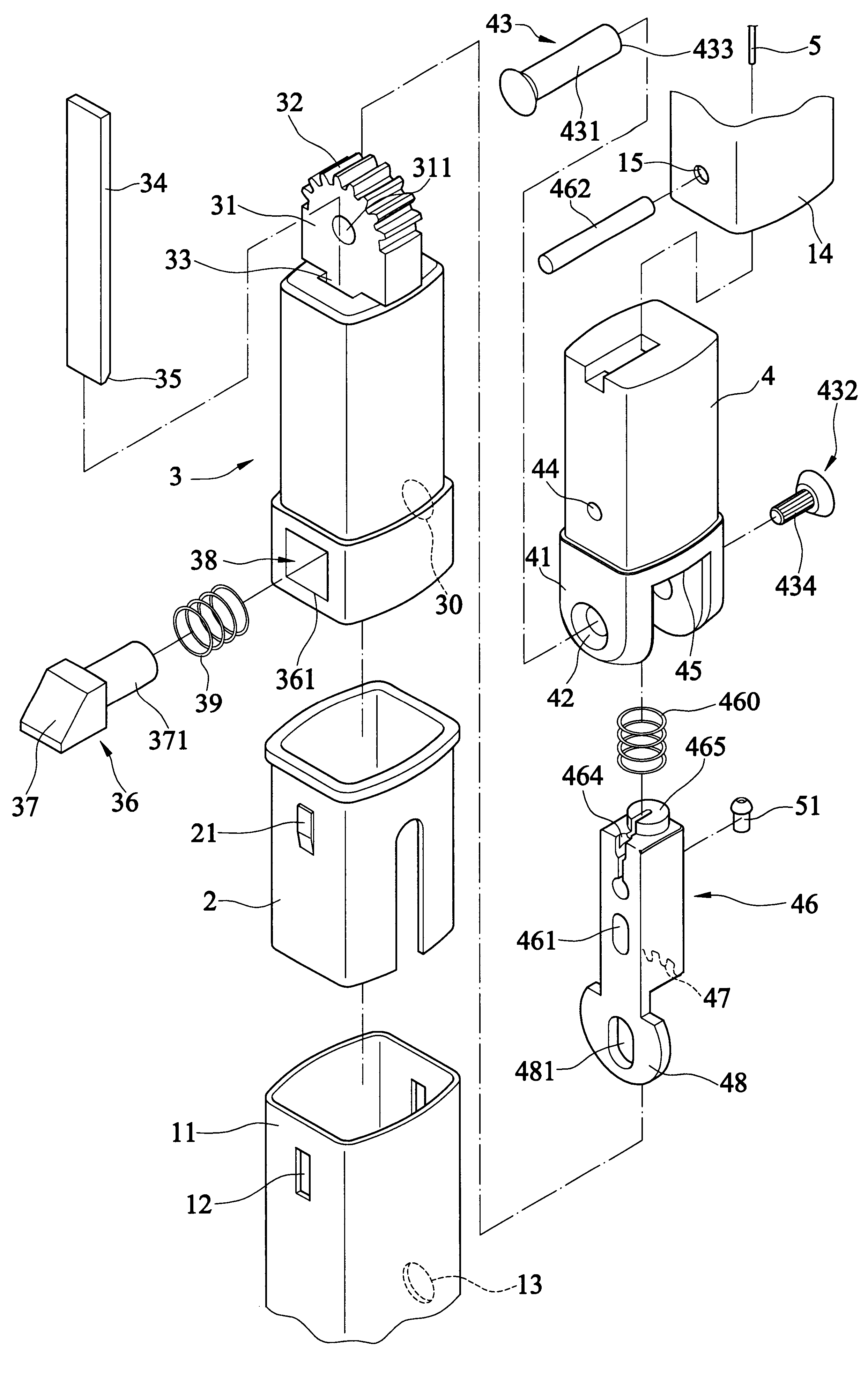
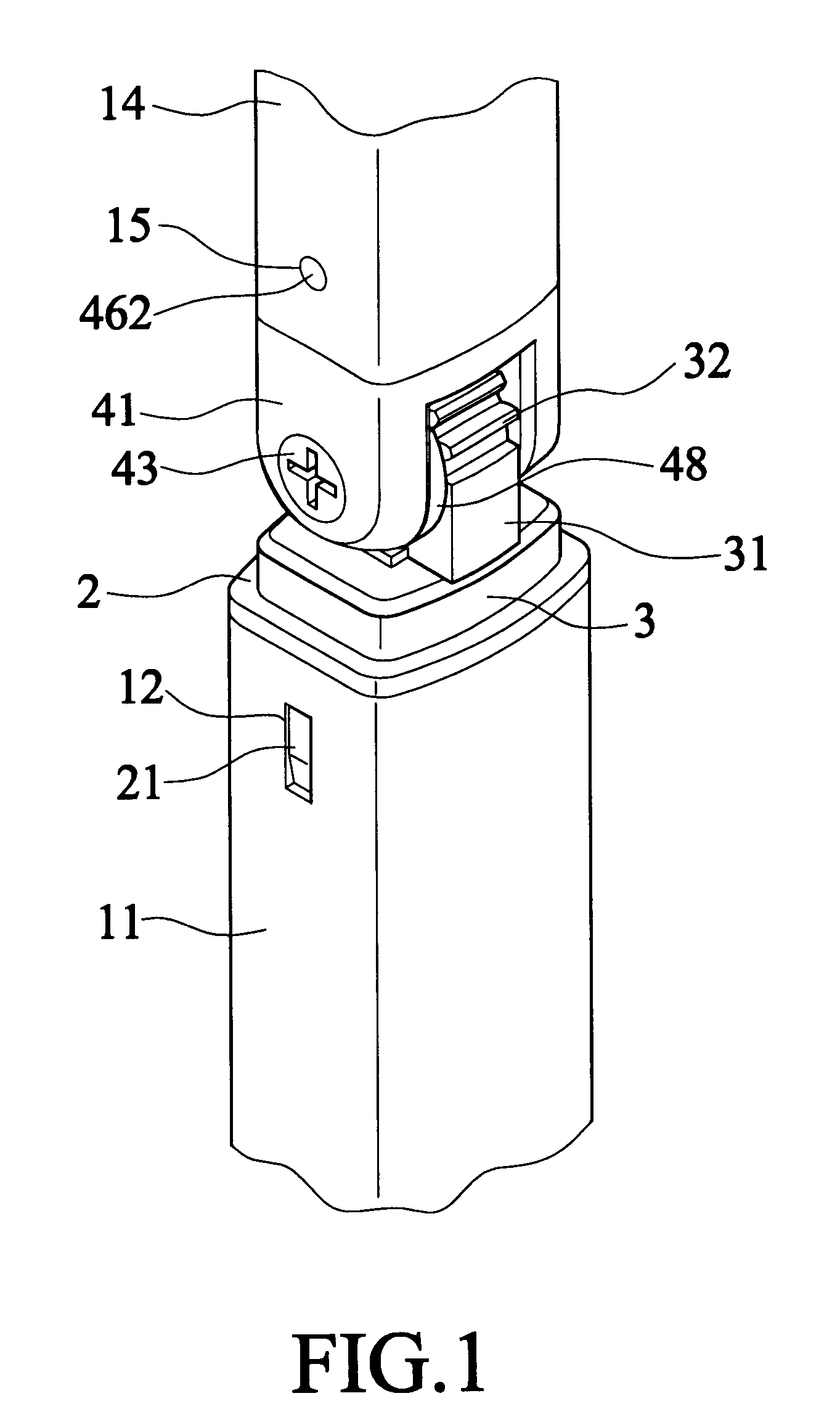
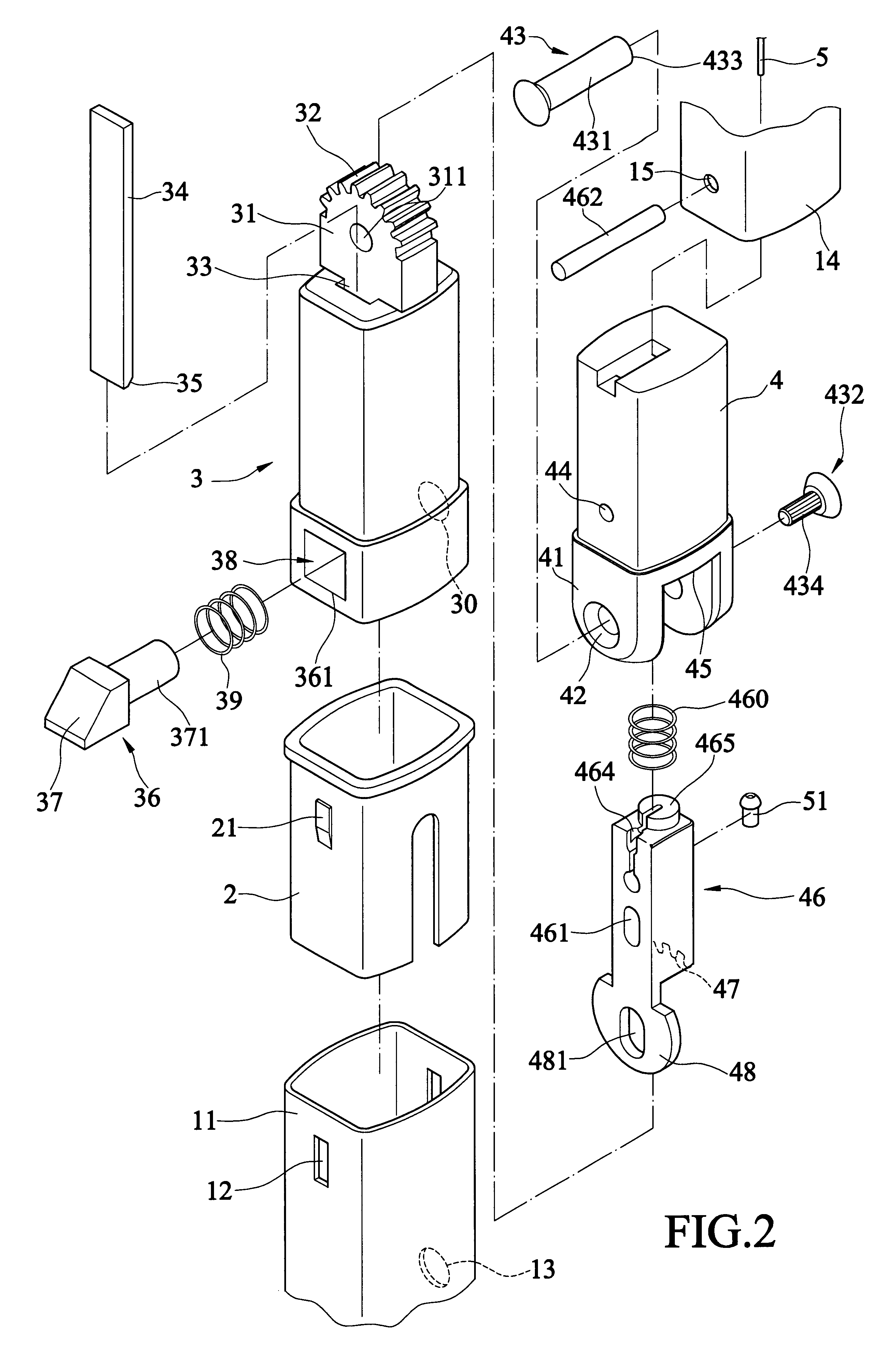
FIGS. 1 to 7 show a swivel draw bar structure of a suitcase according to the present invention, wherein FIGS. 1 to 4 illustrate the present invention mainly with a two-joint type draw bar. A draw bar 1 comprises a lower joint tube 11 and an upper joint tube 14. A fixing sleeve 3 is installed at the top end of the lower joint tube 11 of the draw bar 1. A projective arc plate 31 is joined at the center of the top surface of the fixing sleeve 3. A plurality of teeth 32 are formed on the top surface of the arc plate 3. A downward straight groove 33 is formed on the top surface of the fixing sleeve 3. A slide sheet 34 is inserted in the straight groove 33. The bottom end of the slide sheet 34 is a bevel 35 joined with a bevel 37 of a retractable button 36 so that the retractable button 36 can slide in a transversal groove 38 of the fixing sleeve 3. The retractable button 36 has a square main body penetrating through a square hole 361 of the transversal groove 38. The inner end of retract...


PUM


Abstract

A swivel draw bar structure of a suitcase. A fixing sleeve is installed at the top end of the lower joint tube of the draw bar. A projective arc plate is joined at the center of the top surface of the fixing sleeve. A plurality of teeth are formed on the top surface of the arc plate. A downward straight groove is formed on the top surface of the fixing sleeve. A slide sheet is inserted in the straight groove. The bottom end of the slide sheet is a bevel joined with a bevel of a retractable button so that the retractable button can slide in a transversal groove of the fixing sleeve. The projective part of the retractable button can penetrate through the transversal groove and protrude out of a hole of the fixing sleeve to be locked in a hole of the lower joint tube. A swivel sleeve seat is joined at the bottom end of the upper joint tube. A pair of auriform sheets having holes extend downwards from the swivel sleeve seat. The holes of the auriform sheets are joined a central hole of the arc plate via a spindle. An upward longitudinal groove is formed on the bottom surface of the swivel sleeve seat for insertion of a slide retaining element. The slide retaining element is connected to the swivel sleeve seat through pin connection. The top end of the slide retaining element is joined with a drive element to drive the slide retaining element to move upwards or downwards. A tooth part is formed on the bottom surface of the slide retaining element to mesh with the teeth of the arc plate. A retaining sheet extends from the bottom surface of the slide retaining element. The bottom end of the retaining sheet contacts with the top end of the slide sheet to push the retractable button to be positioned in the lower joint tube.

Description

The present invention relates to a swivel draw bar structure of a suitcase and, more particularly, to a fixing structure which can achieve positioning and locking effects after turned.Along with continual prevalence of travel mood and growing frequency of international business, demand of using traveling suitcases becomes higher and higher. When walking and pulling a suitcase, the best usage is to pull it along an elevation angle of 45 degrees. However, because the height of each person differs, the structure of the suitcase needs to be designed to meet different requirements. A suitcase having a retractable draw bar is the best trap taken along with a traveler. Two-joint type or multiple-joint type draw bars have been widely used in the structure of suitcases, wherein the two-joint type draw bars are more generally used. When the upper joint tube of a two-joint type draw bar is pulled out, only the bottom end of the upper joint tube and the top end of the lower joint tube are posit...

Claims


Application Information

Patent Timeline
IPC IPC(8): A45C13/26A45C13/00
CPCA45C13/262A45C2013/265
Inventor KUO, CHUNG-HSIEN
Owner CHAW KHONG TECH
Why Eureka
Try Eureka