Eureka AIR delivers breakthrough ideas for toughest innovation challenges, trusted by R&D personnel around the world.

Control device for steer-by-wire steering device having redundancy function

a control device and steering device technology, applied in the direction of steering initiation, instruments, vessel construction, etc., can solve the problems of difficult use and inability to hold redundancy, and achieve the effect of improving the steering sensation of the driver, accurate steering, and increasing driving comfor

Inactive Publication Date: 2014-06-19
NTN CORP
View PDF7 Cites 23 Cited by
  • Summary
  • Abstract
  • Description
  • Claims
  • Application Information

AI Technical Summary

Benefits of technology

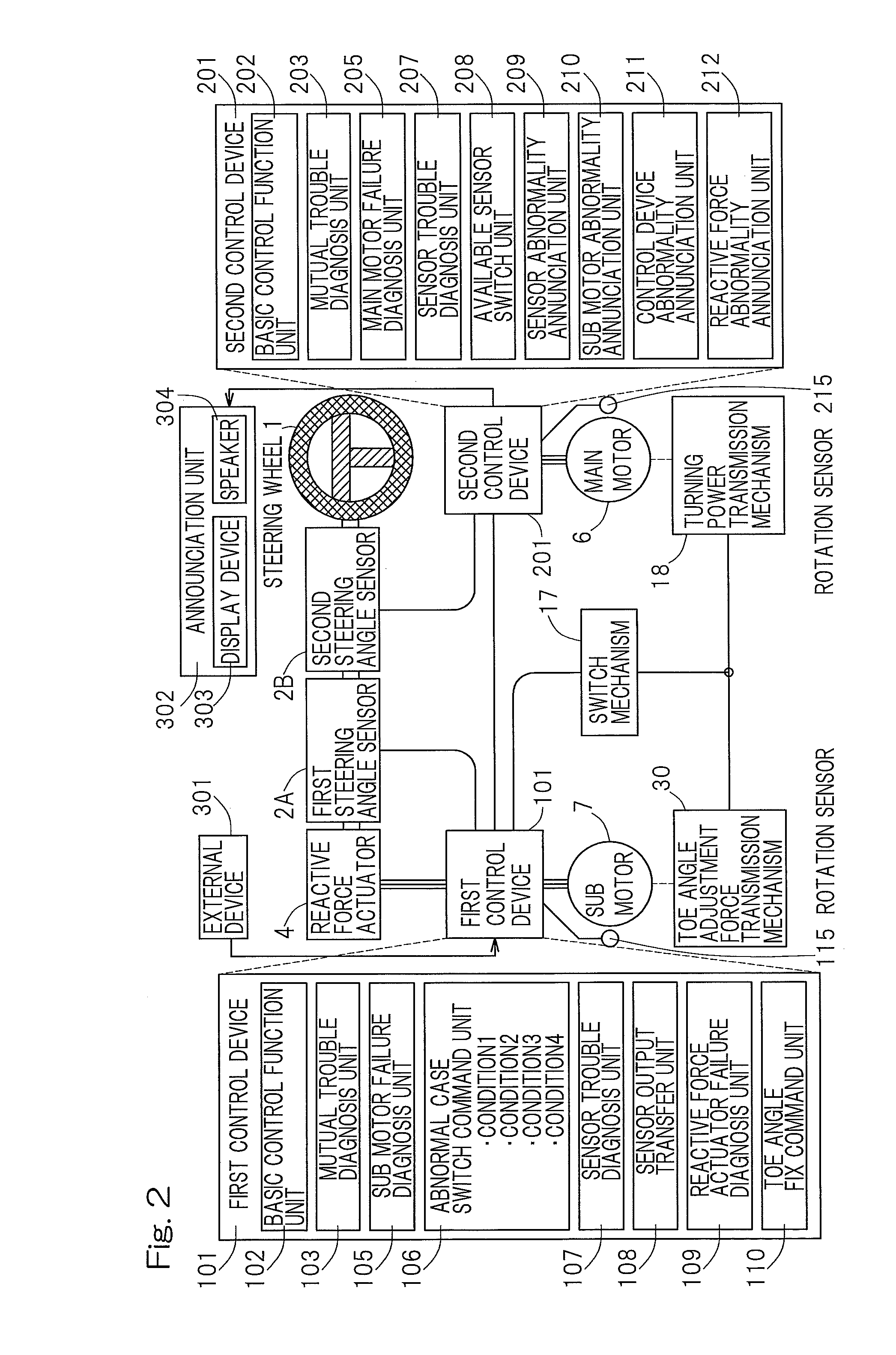
The present invention relates to a steering system for vehicles that includes a first control device and a second control device communicating with each other. The first control device diagnoses a failure in the main motor through a resistive mutual trouble diagnosis unit and a sensor trouble diagnosis unit. The second control device diagnoses a failure in the sub motor through a sensor trouble diagnosis unit. The system includes a switch mechanism that can switch to a toe angle fixed case switched mode to allow the main motor to perform a turning in case of failure of the sub motor. The system also includes a sensor failure diagnosis unit and an abnormality annunciation unit to alert the driver of the sensor failure. The invention provides a safe and reliable steering system that can still control the vehicle even in the event of sensor failure or motor failure.

Problems solved by technology

It has, however, been found that the patent document 2 referred to above is silent as to the use of the fail safe function afforded by a control device such as, for example, an ECU (electric control unit) and no redundancy cannot be held in the event of the failure of the control device.
Although the control redundancy may be obtained when the control device is multiplexed, the mere multiplexing may incur a considerable waste in the control device in the event of such control device functioning properly and, therefore, the use thereof is difficult to achieve.

Method used


Image

  • Control device for steer-by-wire steering device having redundancy function
  • Control device for steer-by-wire steering device having redundancy function
  • Control device for steer-by-wire steering device having redundancy function

Examples


Embodiment Construction

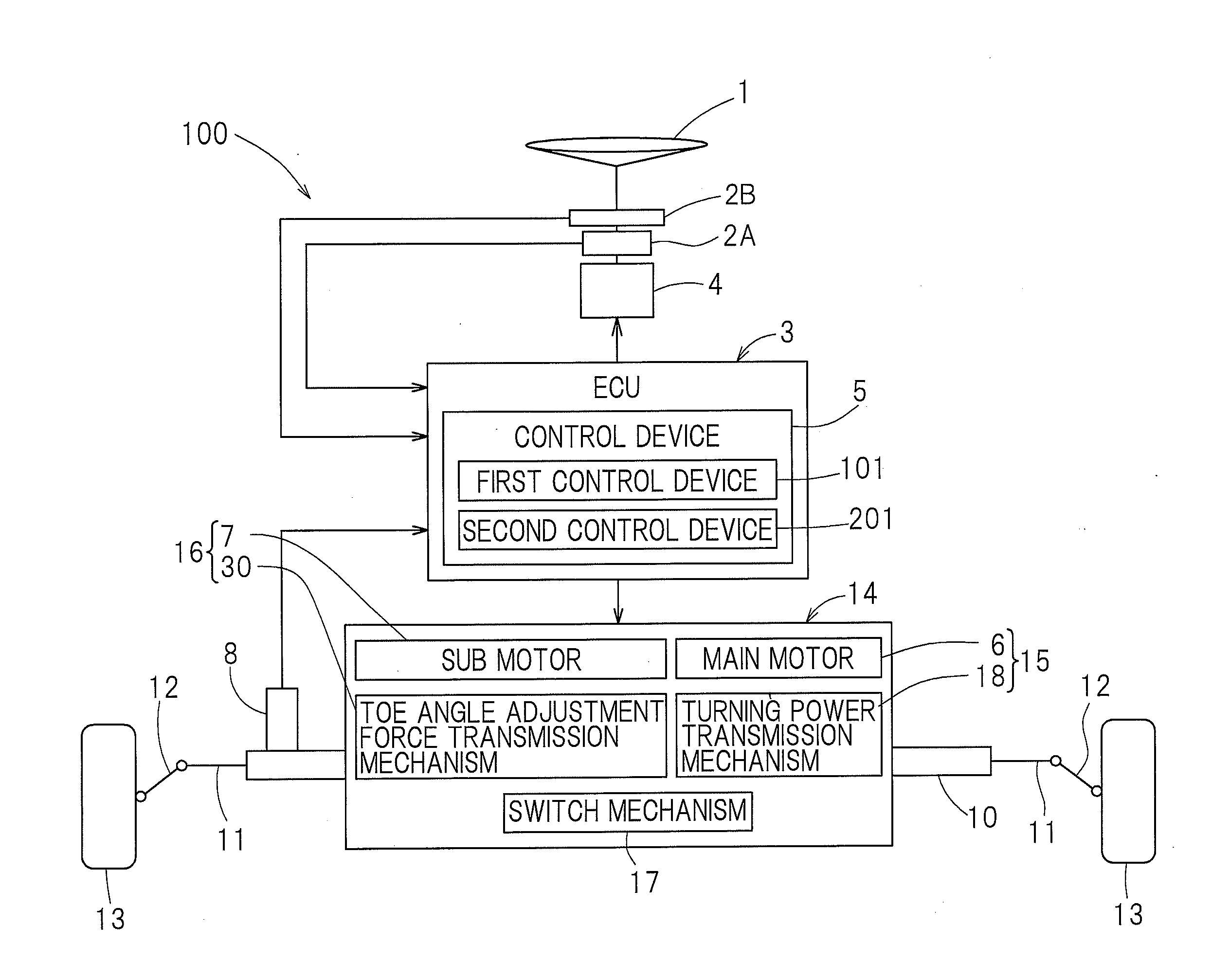
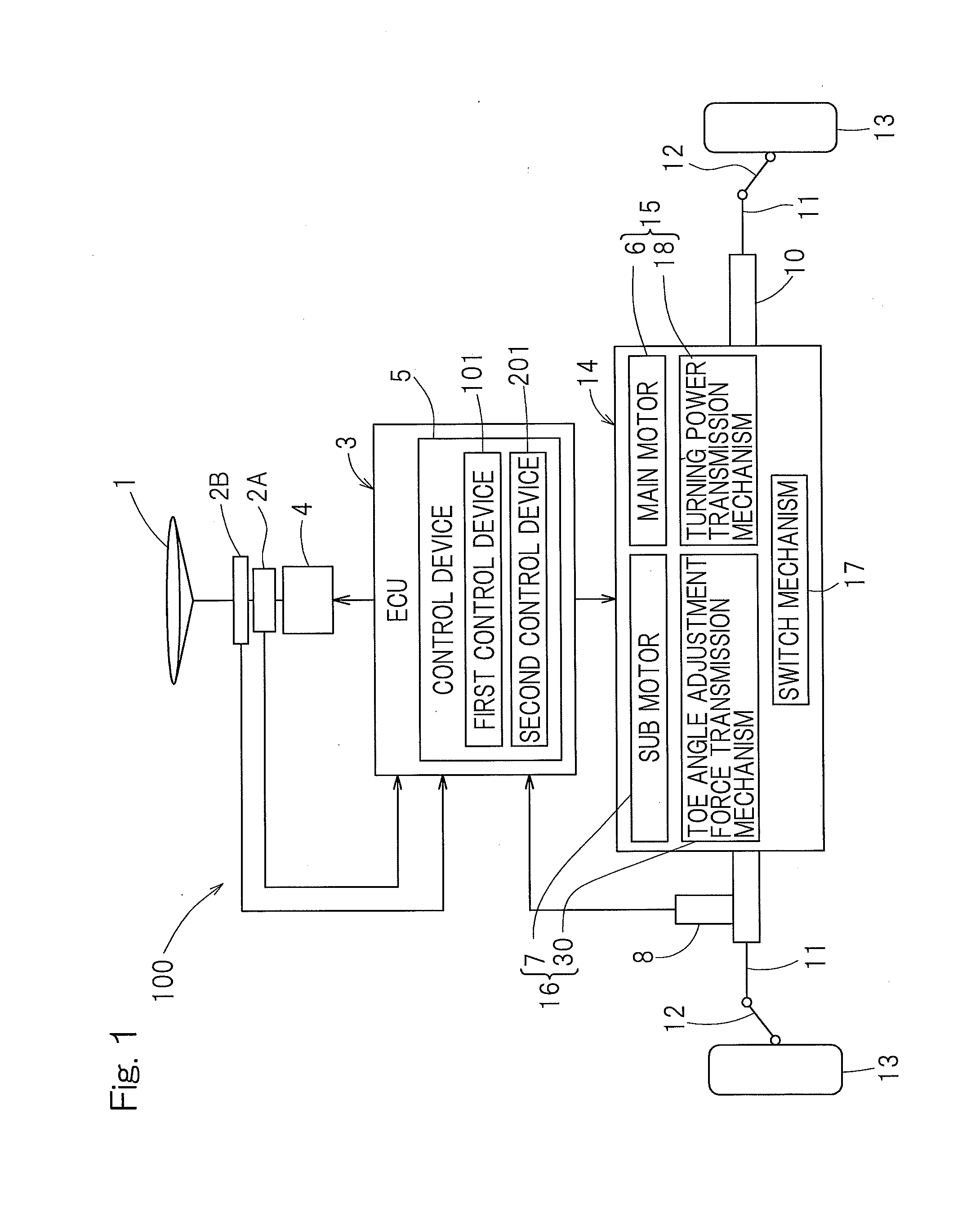
[0055]The present invention will be hereinafter described in detail in connection with some embodiments thereof with reference to FIG. 1 to FIGS. 13A and 13B. In particular, FIG. 1 illustrates a schematic structure of a steer-by-wire steering device 100 and a control unit 5 therefore. The steer-by-wire steering device 100 includes a steering wheel 1 steered by a driver, first and second steering angle sensors 2A and 2B, a steering reactive force actuator 4, a turning shaft 10 for turning use, which is configured to be movable axially and is connected with left and right steered wheels 13 through respective knuckle arms 12 and tie rods 11, a turning shaft drive unit 14 for driving the turning shaft 10, and a turning angle sensor 8. The turning shaft 10 has a telescopically movable and separable structure such that, in addition to the turning brought about by the axial movement of the entirety of the turning shaft 10, a toe angle adjustment may be performed by the telescopic movement ...


PUM


Abstract

A control device for controlling a steer-by-wire steering control device includes a switch mechanism for detaching a main motor and transmitting a rotation of a sub motor to establish a failsafe mode in which a turning is possible. A first control device controls a reactive force actuator and the sub motor. A second control device drives a main motor. The first control device has an abnormal case switch command unit and, when receiving a result of diagnosis that the main motor fails to operate properly, or when the mutual trouble diagnosis unit diagnoses that the second control device is in a trouble, the switch mechanism is set to the failsafe mode.

Description

CROSS REFERENCE TO THE RELATED APPLICATION[0001]This application is based on and claims Convention priority to Japanese patent application No. 2011-167090, filed Jul. 29, 2011, the entire disclosure of which is herein incorporated by reference as a part of this application.BACKGROUND OF THE INVENTION[0002]1. Field of the Invention[0003]The present invention relates to a steer-by-wire steering device of a kind capable of accomplishing a steering with a steering wheel that is not mechanically connected with a turning shaft for turning use and, more particularly, to a control device for the steer-by-wire steering device of a type having a redundancy function in which a mechanical system and a control device are provided with respective redundancies.[0004]2. Description of Related Art[0005]A device such as, for example, a turning device, which is likely to result in a serious accident when a trouble occurs therein, a high degree of redundancy is needed. As a measure to deal with it, a s...

Claims


Application Information

Patent Timeline
Patent Type & Authority Applications(United States)
IPC IPC(8): B62D6/00
CPCB62D6/00B62D5/003
Inventor NISHIKAWA, AKIYOSHIOKADA, KOICHINAKAJIMA, AKIOZHANG, YINGJIE
Owner NTN CORP
Why Eureka
Eureka Blog
Learn More