Optical switch using risley prisms

a technology of optical switch and prism, applied in the field of optical switch, can solve the problems of slow and complex electronic switching, inability to adapt to the large increase in network bandwidth, and inability to achieve the effect of precise, independent rotation

Inactive Publication Date: 2005-02-22
NAT TECH & ENG SOLUTIONS OF SANDIA LLC
View PDF14 Cites 22 Cited by
  • Summary
  • Abstract
  • Description
  • Claims
  • Application Information

AI Technical Summary

Benefits of technology

Each wedge prism of each input and output Risley prism pair is rotated independently by a rotary microactuator. The rotary microactuator can comprise a cylindrically symmetric electromagnetic stator and an annular soft ferromagnetic rotor that can be patterned with magnetically salient, variable-reluctance pole faces suitable for small angle stepping to provide precise, independent rotation of each wedge prism of a Risley prism pair.

Problems solved by technology

However, network transmission speeds and equipment costs are currently severely limited by the requirement of slow and complex electronic switching for signal routing—converting an optical (i.e., photonic) signal from an input optical fiber into an electronic signal, switching the lower speed electronic signal, converting the electronic signal back to an optical signal, and redirecting the optical signal through an output optical fiber.
In particular, it is unlikely that such optoelectronic switching will be able to accommodate the large increase in network bandwidth that will accompany the full implementation of DWDM.
However, none of these technologies are likely to satisfy a wide range of applications, as the requirements for optical fiber array size, scalability, switching speed, reliability, optical loss, cost, and power consumption differ greatly depending on the functionality desired.
However, such a MEMS switch is complex.
Furthermore, switching times can be slow and the long-term reliability of moveable parts is a concern.

Method used


Image

  • Optical switch using risley prisms
  • Optical switch using risley prisms
  • Optical switch using risley prisms

Examples


Embodiment Construction

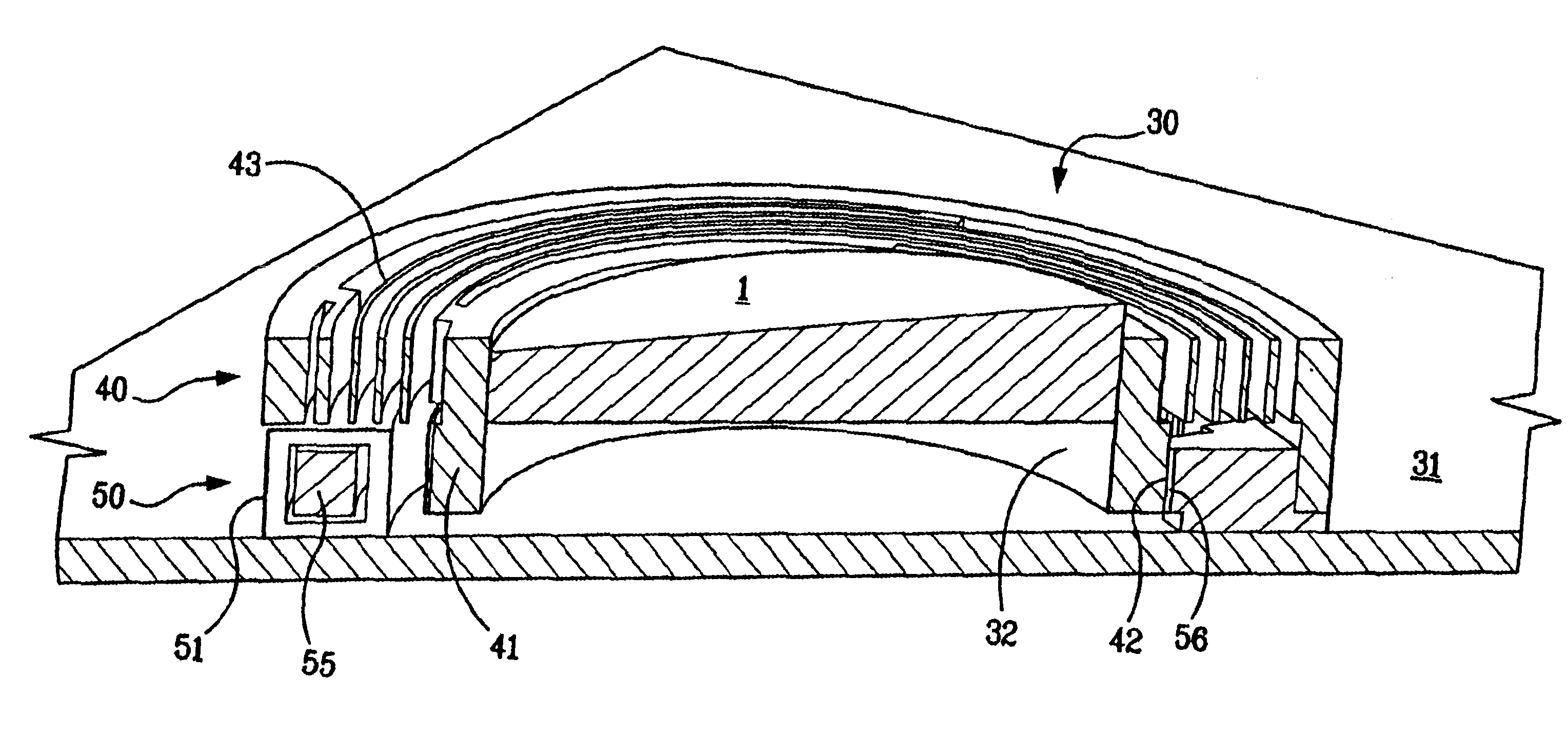
The invention comprises an optical switch comprising two or more Risley prism pairs for selectively switching an incident light beam from any input fiber of a plurality of input optical fibers to any output fiber of a plurality of output optical fibers. The optical switch uses independent rotation of each wedge prism of input and output Risley prism pairs to redirect the incident light beam to a selected output fiber. The invention further comprises a rotary microactuator that can be formed integrally with each wedge prism for precise rotation thereof. The rotary microactuator can be fabricated by a seven-layer LIGA process. The integral wedge prism can be fabricated by a DXRL process. The optical switch using Risley prisms and a method for fabricating the optical switch and the rotatable wedge prism assembly are described below.

Optical Design of the Optical Switch

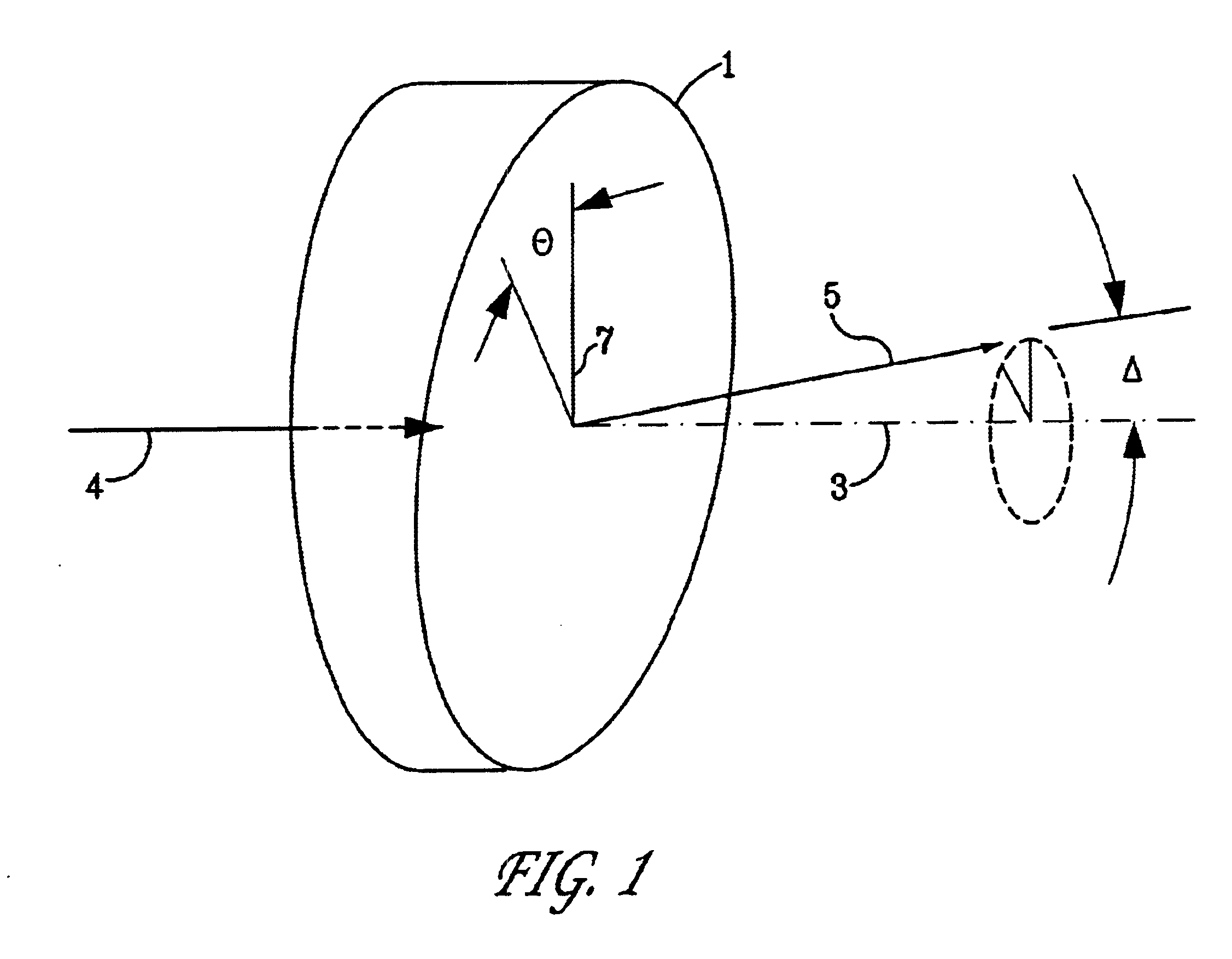
A prism can be used to change the direction of propagation of an incident beam of light. As shown in FIG. 1, a wedge pri...


PUM


Abstract

An optical switch using Risley prisms and rotary microactuators to independently rotate the wedge prisms of each Risley prism pair is disclosed. The optical switch comprises an array of input Risley prism pairs that selectively redirect light beams from a plurality of input ports to an array of output Risley prism pairs that similarly direct the light beams to a plurality of output ports. Each wedge prism of each Risley prism pair can be independently rotated by a variable-reluctance stepping rotary microactuator that is fabricated by a multi-layer LIGA process. Each wedge prism can be formed integral to the annular rotor of the rotary microactuator by a DXRL process.

Description

BACKGROUND OF THE INVENTIONThe optical switch of the present invention comprises Risley prisms (i.e., pairs of wedge prisms) to redirect light beams from an array of input ports to an array of output ports. The invention further comprises a stepping rotary microactuator for independent rotation of each wedge prism of a Risley prism pair to redirect the light beams.As the demand for network capacity grows, telecommunications are being increasingly constrained by the need for more bandwidth. Optical fiber is a transmission medium capable of meeting this demand, having the potential in combination with dense wavelength division multiplexing (DWDM) to provide carrying capacity in a single fiber of hundreds of trillions of bits (terabits) per second, far greater than other means suggested for long-distance communications.However, network transmission speeds and equipment costs are currently severely limited by the requirement of slow and complex electronic switching for signal routing—co...

Claims


Application Information

Patent Timeline
Patent Type & Authority Patents(United States)
IPC IPC(8): G02B6/35
CPCG02B6/3524G02B6/3528G02B6/3584G02B6/3572G02B6/3556
Inventor SWEATT, WILLIAM C.CHRISTENSON, TODD R.
Owner NAT TECH & ENG SOLUTIONS OF SANDIA LLC
Why Eureka
Try Eureka