
Masonry line block and corner pole

a technology of corner poles and bricks, applied in the field of masonry line blocks and corner poles, can solve the problems of inefficiency, time-consuming, tedious present methods for forming decorative quoins, etc., and achieve the effect of quick and safe bricklaying

Inactive Publication Date: 2002-07-02
HEAVNER CHARLES EDDIE
View PDF7 Cites 23 Cited by
  • Summary
  • Abstract
  • Description
  • Claims
  • Application Information

AI Technical Summary

Benefits of technology

to provide an easy-to-use masonry line block for use in combination with a corner pole and guide line which enables a mason to lay bricks quickly, safely, and in proper alignment without the use of a level or rule.
It is another object of the invention to provide a masonry line block for use in combination with a corner pole and guide line which enables ready and accurate construction of decorative quoins formed in brick structures.
It is another object of the invention to provide a masonry line block for use in combination with a corner pole and guide line which affords the mason freer use of his hands by reducing efforts otherwise required to ensure proper placement and alignment of bricks.
It is another object of the invention to provide a masonry line block for use in combination with a corner pole and guide line which reduces overall construction costs by speeding up the construction process.

Problems solved by technology

Present methods for forming decorative quoins are tedious and time consuming.
The problems result largely from the design of the cooperating line blocks used to carry the tensioned guide line.
This technique is inefficient and relatively labor intensive Moreover, because the guide line is tensioned between the corner poles, it is not uncommon for a line block to inadvertently slip off a corner pole and strike a nearby worker causing injury.

Method used


Image

  • Masonry line block and corner pole
  • Masonry line block and corner pole
  • Masonry line block and corner pole

Examples


Embodiment Construction

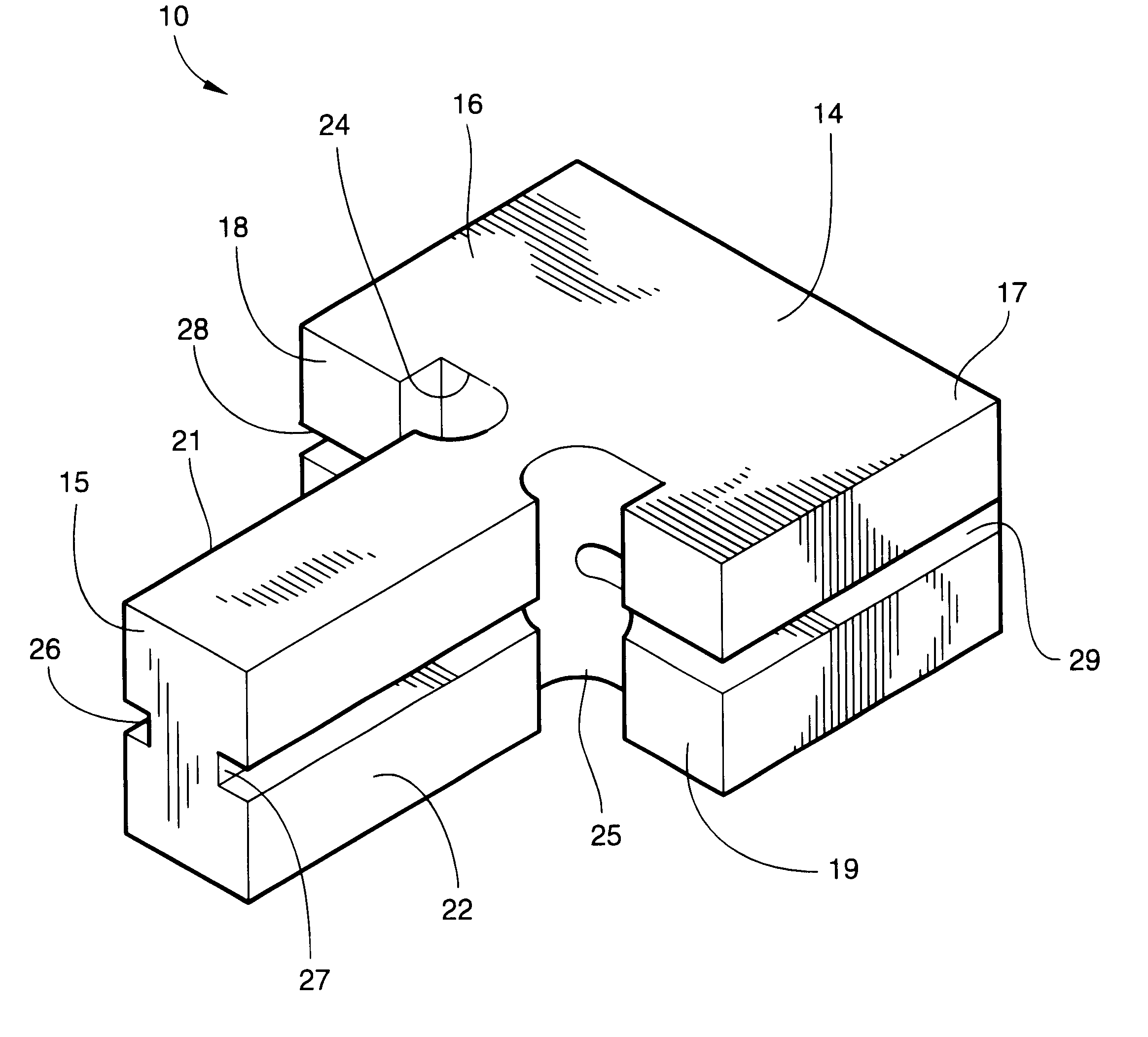
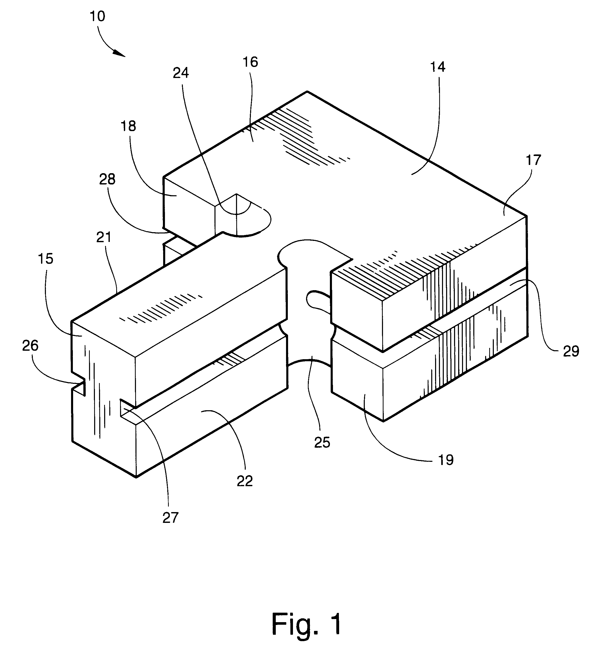
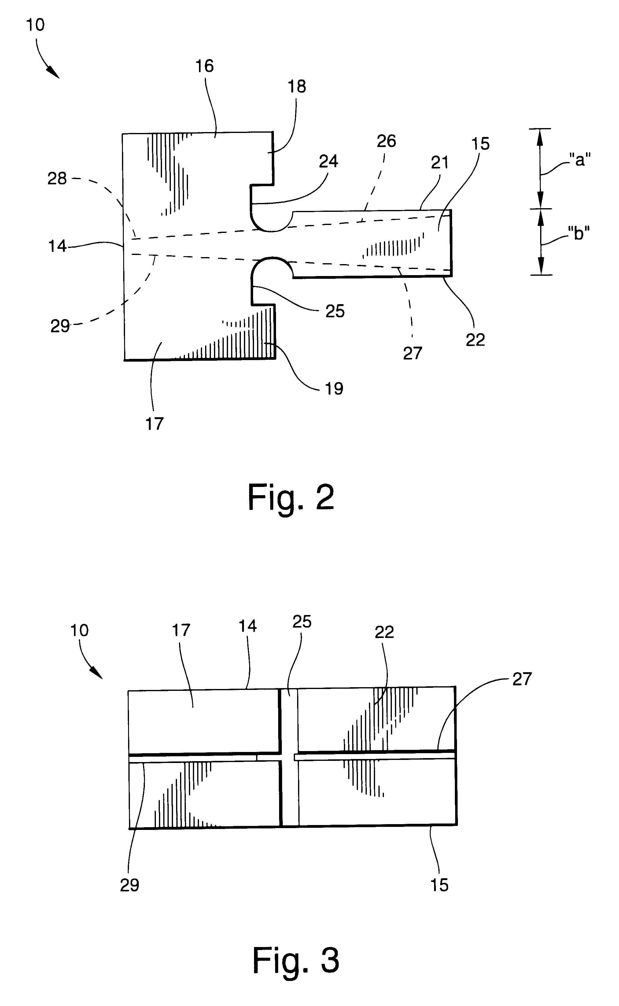
Referring now specifically to the drawings, a masonry line block according to the present invention is illustrated in FIG. 1 and shown generally at reference numeral 10. The line block 10 is generally used in pairs in combination with a masonry corner pole 11, such as shown in FIGS. 6-10, to construct a brick structure "S" including decorative quoins "Q". The decorative quoins "Q" are formed at the junction of intersecting brick walls "W", and are defined by overlying bricks arranged to project slightly outwardly from respective exterior surfaces of the brick walls "W". The decorative quoins "Q" are vertically spaced-apart along one or more corners of the brick structure "S". The line blocks 10 and 10' cooperate with the corner pole 11 and respective line holders (not shown) located at opposite ends of each brick wall "W" to carry respective tensioned guide lines 12 and 12' used to maintain proper placement and alignment of the brick courses. The line holders may be additional corne...


PUM


Abstract

A masonry line block is adapted for use in combination with a vertical corner pole during construction of a structure. The structure has an exterior surface and at least one surface projecting from the exterior surface. The line block engages the corner pole at one end of the structure and cooperates with a line holder located at an opposite end of the structure to carry a tensioned guide line therebetween. The guide line indicates proper placement and alignment of building units used to form the structure. The line block includes a mounting member having first and second, opposing pole-engaging shoulders. The shoulders are adapted for selectively engaging the corner pole to hold the line block in one of first and second alignment positions relative to the structure. An alignment member is formed with the mounting member and extends perpendicularly outwardly from the pole-engaging shoulders. The alignment member has first and second opposing sides and defines a thickness corresponding generally to a distance between the outer surface of the structure and the projecting surface of the structure. In the first alignment position of the line block, the alignment member is adapted for locating the guide line relative to the structure to indicate proper placement and alignment of building units used to form the exterior surface of the structure. In the second alignment position of the line block, the alignment member is adapted for locating the guide line relative to the structure to indicate proper placement and alignment of building units used to form the at least one projecting surface of the structure.

Description

TECHNICAL FIELD AND BACKGROUND OF INVENTIONThis invention relates to a masonry line block and corner pole used during formation of a structure, such as a residential home, commercial building, privacy wall, and the like. The line block engages the corner pole at one end of the structure and cooperates with a line holder located at an opposite end of the structure to carry a tensioned guide line. The guide line indicates proper placement and alignment of building units, such as bricks or concrete blocks, used to form the structure. The invention is especially applicable for forming decorative quoins common in many residential homes. The decorative quoin, are formed at the junction of intersecting brick walls, and are defined by overlying bricks arranged to project slightly outwardly from respective exterior surfaces of the brick walls. The decorative quoins are generally spaced-apart along one or more corners of the brick structure.Present methods for forming decorative quoins are te...

Claims


Application Information

Patent Timeline
IPC IPC(8): E04G21/18G01C15/00
CPCE04G21/1808G01C15/00
Inventor HEAVNER, CHARLES EDDIE
Owner HEAVNER CHARLES EDDIE
Learn More