Life-saving device

a life-saving device and technology of a life-saving device, applied in life-saving, waterborne vessels, cast lines, etc., can solve the problems of poor buoyancy, difficult redeployment, and no rescue device currently available to incorporate or be able to incorporate all of the above features

Inactive Publication Date: 2002-07-02
LIFESAFER
View PDF6 Cites 10 Cited by
  • Summary
  • Abstract
  • Description
  • Claims
  • Application Information

AI Technical Summary

Problems solved by technology

None of the currently available rescue devices incorporate or are able to incorporate all of the aforementioned features.
Unfortunately while the device meets some of the desired features for a life saving device it has poor buoyancy and is difficult to redeploy if the first attempt at reaching the victim fails.
In addition the device may also cause injury if it hits the victim during rescue.
Likewise the standard life ring and seat cushion / floatation devices meet many of the desirable features for a life saving device, however they fail in other critical aspects.
Often these devices do not have a retrieval line that enables a rescuer to retrieve and redeploy the device if the victim is not reached or is missed on the first throw or toss.
Although some standard life rings include an attached retrieval line, the life ring may have the tendency to dive during retrieval, which jeopardizes the safety of the victim and slows retrieval time.
Flying rescue disks with retrieval line retention and deployment features on or about the outside perimeter of the disk like those described in U.S. Pat. Nos. 5,562,512 and 5,895,299 also meet some of the desirable features of a life saving device, however, they suffer from lack of aerodynamic efficiency due to the interference caused by the location of the line retention and deployment features in aerodynamic areas critical for performance.
In addition, their buoyancy is generally poor and their potential for injuring the victim is high because of their hard body construction.
Some flying rescue disks incorporate a hollow flotation compartment defined by a hard plastic encapsulation to increase buoyancy, unfortunately they can be damaged by rough handling or impact, which may allow water to flood the compartment or otherwise decrease the disk's functionality.
In addition, the retrieval lines of these devices are affixed to their leading edge and consequently during rescue the devices have a tendency to dive under water upon retrieval jeopardizing the safety of the victim and extending retrieval time.
Also, for a more effectively redeployment of these devices, the retrieval line should be partially rewound around the outer perimeter to allow for free. rotation of the disk, which may further delay rescue time.

Method used


Image

  • Life-saving device
  • Life-saving device
  • Life-saving device

Examples


embodiment 1

VI. Embodiment 1

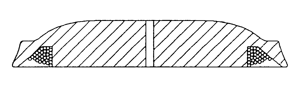
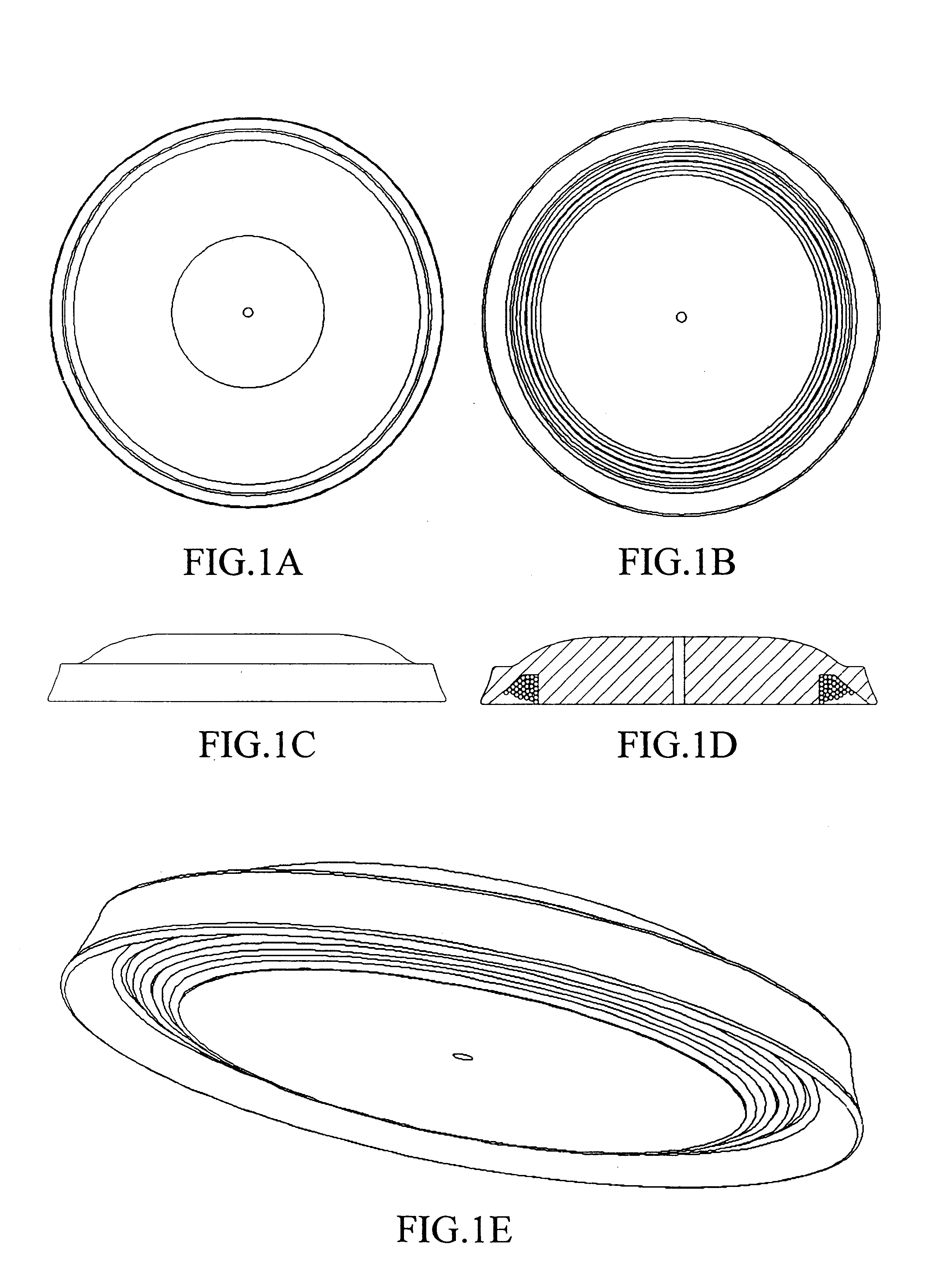
In one embodiment of the invention a life-saving device is provided comprising a buoyant disk having a top side, a bottom side, a leading edge and a cavity on the bottom side along and adjacent to the leading edge. The cavity has an inner side generally parallel to the leading edge and distant from the center of the buoyant disk. A length of line is affixed to the buoyant disk and disposed around the inner side of the cavity. The line is preferably affixed to the buoyant disk through an orifice about the center of the disk which is oriented approximately parallel to the leading edge. The diameter of the orifice is preferably larger than the diameter of the line so that the line may move freely within the orifice. The line is generally inserted through this orifice from the top side of the buoyant disk and fitted with an adapter to secure the line to the buoyant disk.

Preferably the line is approximately 100 feet in length and secured at the bottom sides of the buoyant...

embodiment 2

V. Embodiment 2

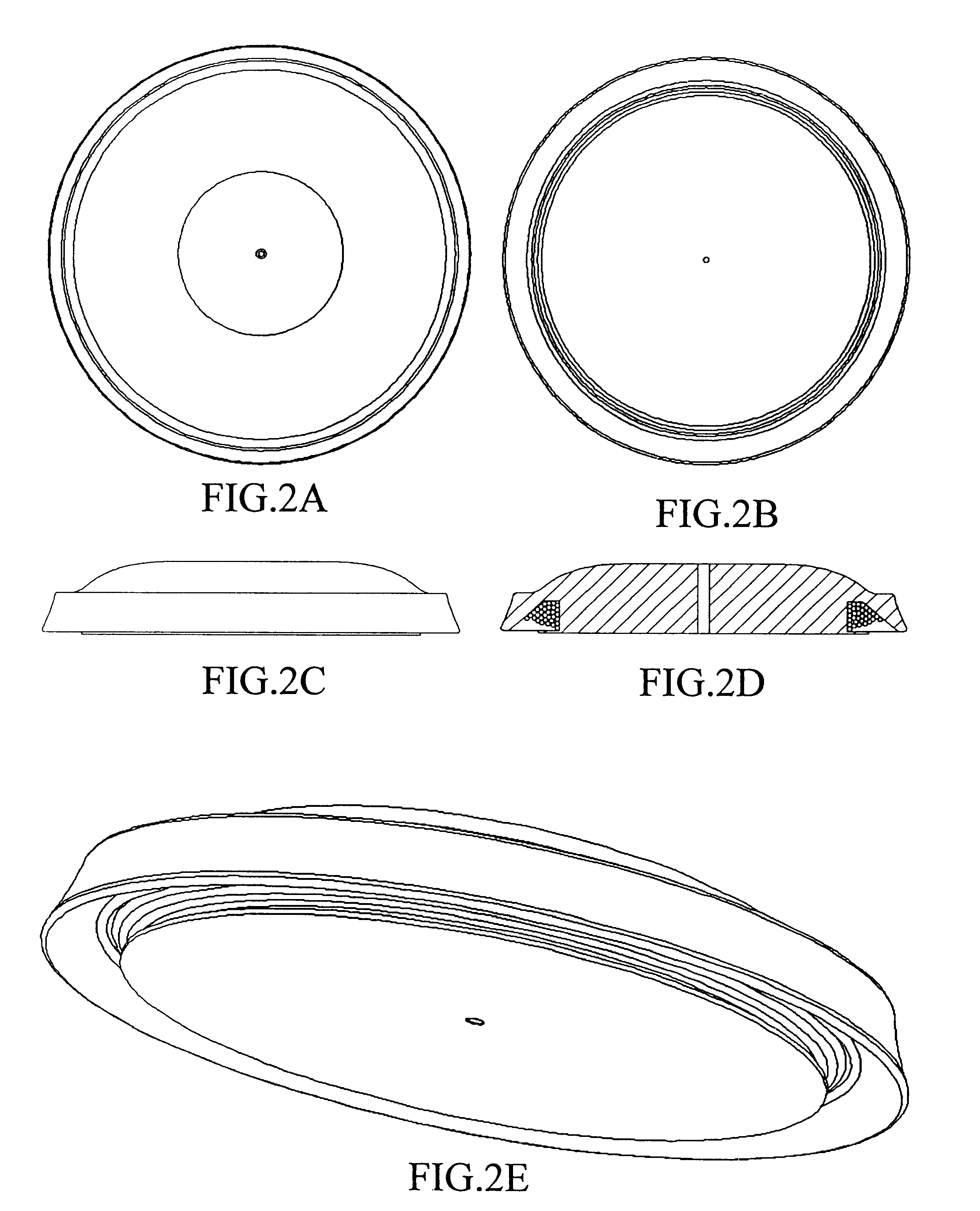
In another embodiment of the invention a life-saving device is provided comprising a buoyant disk having a top side, a bottom side, a leading edge and a cavity on the bottom side along and adjacent to the leading edge. The cavity generally has an inner side distant from the center of the buoyant disk and an outer side more distant from the center of the buoyant disk than the inner side. The device further includes a base plate having an upper surface and a lower surface and a diameter generally less than that of the buoyant disk and overlapping the cavity. The base plate preferably overlaps the cavity approximately 50% to allow retention of the line when the device is stored and for rapid deployment of the line during use. The upper surface of the base plate preferably has a hollow tube portion projecting perpendicular from its center. The hollow tube portion has a diameter able to accept a line and of a length generally equal to the thickness of the buoyant disk. The...

embodiment 3

VI. Embodiment 3

In yet another embodiment of the present invention a life-saving device is provided comprising a buoyant disk having a top side, a bottom side, a leading edge and a cavity disposed on the bottom side along and generally adjacent to the leading edge of the buoyant disk. The cavity has an inner side distant from the center of the buoyant disk and an outer side more distant from the center of the buoyant disk than the inner side. The cavity is able to accept a length of line disposed around the inner side. This device further comprises a base plate having an upper surface and a lower surface. The lower surface of the base plate is preferably domed. The diameter of the base plate is generally less than that of the buoyant disk and overlaps the cavity approximately 50% to allow retention of the line when the device is stored and for rapid deployment of the line during use. The upper surface of the base plate is affixed to the bottom side of the buoyant disk.

A hollow tube ...


PUM


Abstract

A novel life-saving device comprising a buoyant disk having a top side, a bottom side, a leading edge and a cavity on the bottom side along and adjacent to the leading edge, the cavity having an inner side generally parallel to the leading edge the inner side having an upper edge and a lower edge and a length of line affixed through and about the center of the buoyant disk generally parallel to the leading edge and disposed around the inner side of the cavity.

Description

The invention relates to floatation devices for aquatic rescue more particularly to a hand thrown life saving device.BACKGROUND OF INVENTIONIn 1998 the World Health Organization reported 119,000 drownings worldwide with approximately 5,000 of those occurring in the United States alone according to the American Red Cross. Data collected by the International Lifesaving Association indicates that most of these drownings occurred within 60 seconds and according to the statistics of the National Safety Council there has been no significant decline in the fatality rate for drowning victims over the past two decades.The American Red Cross advises that the untrained and inexperienced would-be rescuer follow the rule "Reach, Throw, Don't Go". The rule recommends that if the drowning victim cannot be reached, or if a flotation aid or retrieval device cannot be thrown to the drowning victim that the rescuer should not attempt an open water rescue. For these types of non-professional rescue att...

Claims


Application Information

Patent Timeline
Patent Type & Authority Patents(United States)
IPC IPC(8): B63C9/26B63C9/08B63C9/00
CPCB63C9/08B63C9/26
Inventor WAHL, MICHAELDRISCOLL, PAUL K.DORITY, JOHN B.
Owner LIFESAFER
Why Eureka
Try Eureka