Power-off damping in MR damper

a technology of damper and damping plate, which is applied in the field of mr dampers to achieve the effect of more operating range and higher damping minimum level

Inactive Publication Date: 2002-07-16
DELPHI TECH INC +1
View PDF7 Cites 52 Cited by
  • Summary
  • Abstract
  • Description
  • Claims
  • Application Information

AI Technical Summary

Benefits of technology

The present invention is a MR damper that provides a higher than minimum level of damping when a power source to the MR damper is not supplying a control current. The damper of the present invention includes permanent magnets positioned to direct a magnetic flux across a MR fluid path causing a resistance to MR fluid flow. An electric coil cancels an affect of the permanent magnets when the control current is available to allow a control circuit more operating range. The permanent magnets allow for damping when no control current is available.

Problems solved by technology

This presents obvious problems in that a current must be constantly supplied to the damper in order to provide a greater than minimum dampening effect by the MR damper.

Method used


Image

  • Power-off damping in MR damper
  • Power-off damping in MR damper

Examples


Embodiment Construction

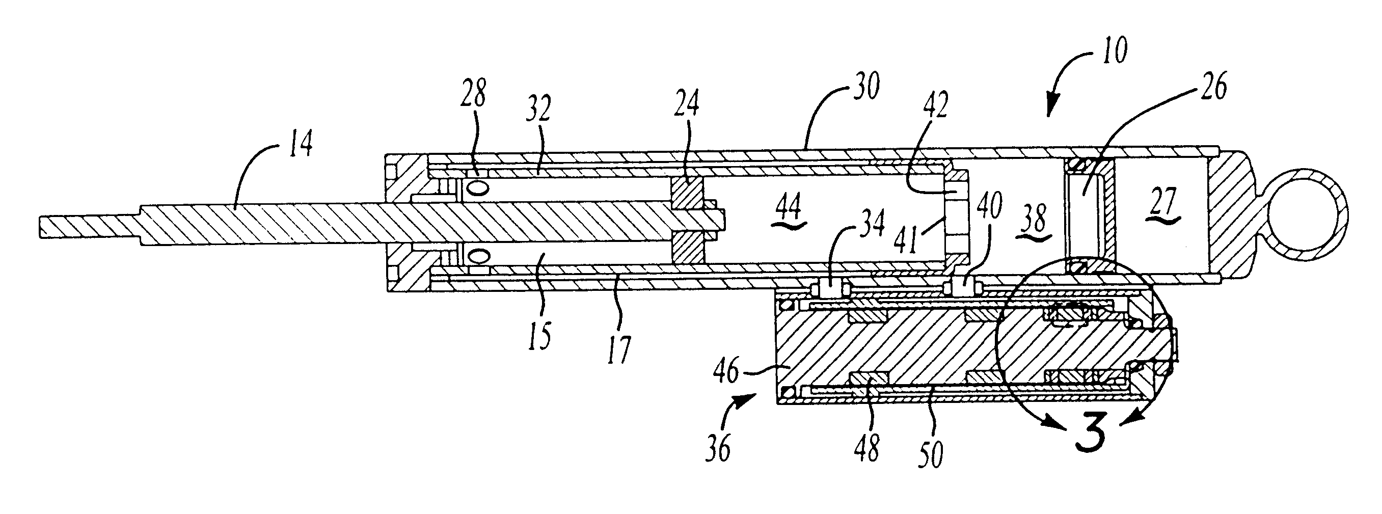
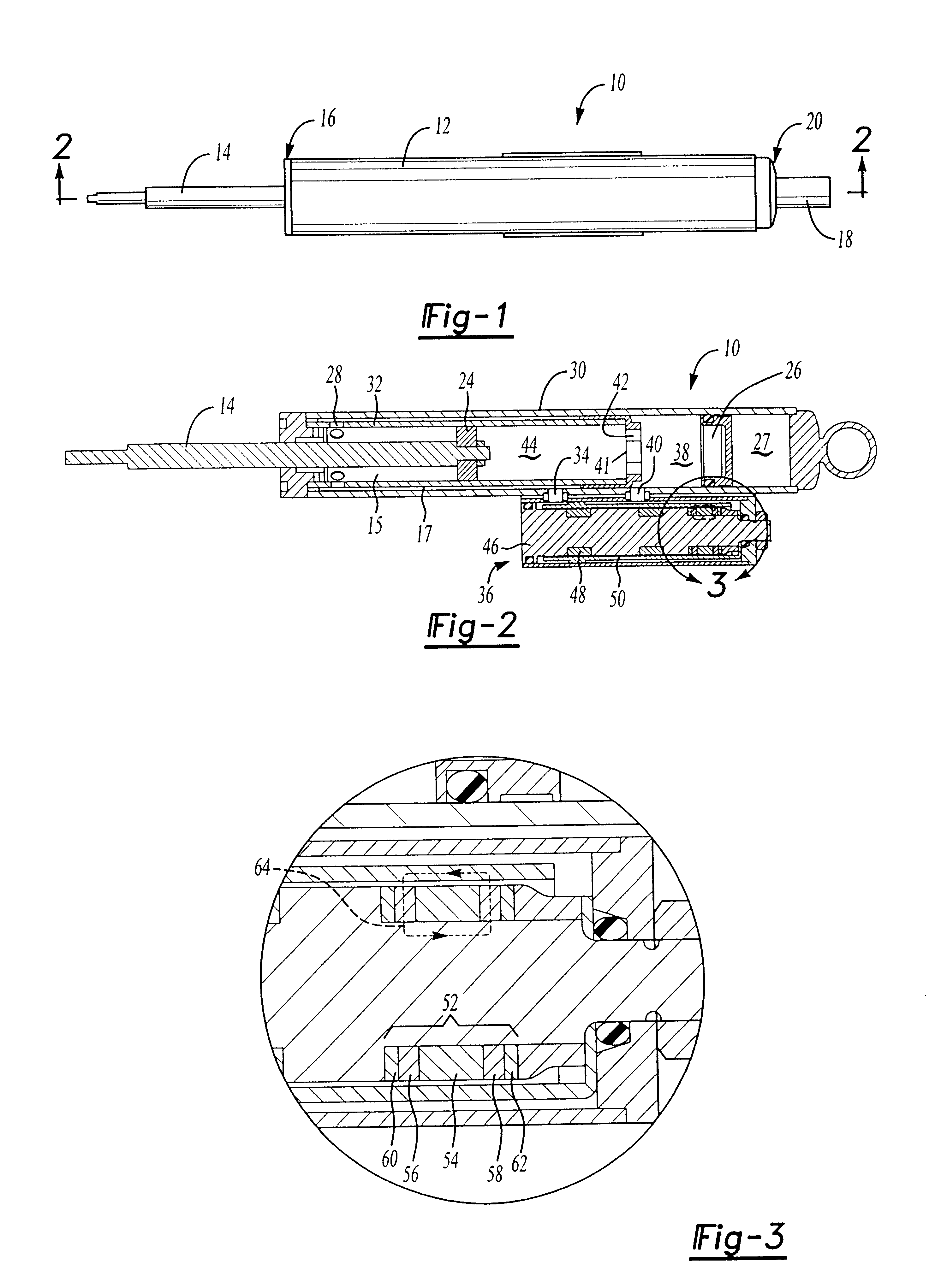
In FIG. 1 a magneto-rheological (MR) damper assembly of the present invention is shown generally at 10. The MR damper assembly comprises a cylindrical housing 12, a rod 14 exiting a first end 16 of the housing 12, and an attachment assembly 18 exiting a second end 20 of the housing 12.

In FIG. 2, a cross section of the MR damper assembly 10 is shown. The MR damper assembly 10 is comprised of a rod 14 attached to a piston 24 and a gas cup 26. The interior chamber 15 is filled with MR fluid. An area 27 partitioned by the gas cup 26 contains a pressurized gas. The gas cup 26 and pressurized gas allow for fluid volume changes due to thermal expansion and displacement due to rod 14 movement. As will be appreciated by those skilled in the art, the piston 24 has no control valving. The damper assembly 10 is configured so that a stroking of the rod 14 and the piston 24 forces fluid through a side mounted control valve 36. When the rod 14 is moved or stroked out of the assembly 10 (a rebound ...


PUM


Abstract

A magneto-rheological (MR) damper provides a higher than minimum level of damping when a power source to the MR damper is not supplying a control current. The present invention damper includes magnets positioned to direct a magnetic flux across a MR fluid path. The fluid path is created when a rod and piston assembly stroke the fluid though a control valve assembly attached to a damper chamber causing a resistance to MR fluid flow. An electric coil cancels an effect of the permanent magnets when the control current is available to allow a control circuit more operating range. The permanent magnets allow for damping when no control current is available.

Description

This invention relates generally to a damper for use between corresponding parts as in a vehicle suspension application. In particular the invention deals with magneto-rheological fluid dampers and their ability to provide dampening characteristics in various power states.Traditionally, a damper such as a shock absorber or a strut, is installed between corresponding parts where motion in a first part is to be damped in reference to a second part. A traditional damper consists of a body and a piston attached to a rod. The body has a smooth cylindrical interior surface and has an attachment feature at a closed end. The piston slides on the interior surface of the body, and the rod projects out an open end of the body. The open end where the rod projects is sealed around the rod, allowing only the rod to slide in and out of the body. An end of the rod outside the body has an attachment feature. Sealed inside the body is a liquid used as a damping fluid. Also, inside the damper body is ...

Claims


Application Information

Patent Timeline
Patent Type & Authority Patents(United States)
IPC IPC(8): F16F9/53
CPCF16F9/535
Inventor OLIVER, MICHAEL LESLIEKRUCKEMEYER, WILLIAM CHARLES
Owner DELPHI TECH INC
Why Eureka
Try Eureka