
Magnetorheological devices with permanent magnet field bias

a permanent magnet field and magnetorheological technology, applied in the direction of spring/damper, shock absorber, vibration suppression adjustment, etc., can solve the problems of affecting the electrical system of the vehicle, adversely affecting fuel economy, and undesirable low damping level of no magnetic field applied, so as to reduce the peak current required and the minimum damping level

Active Publication Date: 2014-02-18
BWI CO LTD SA +1
View PDF10 Cites 15 Cited by
  • Summary
  • Abstract
  • Description
  • Claims
  • Application Information

AI Technical Summary

Benefits of technology

The present invention is an MR device that provides higher damping when the power source is not supplying a control current. The device includes a piston, magnetic flux generators, and a permanent magnet. The damping force depends on the rheology of the MR fluid. The coil carrying an electric current acts as an electromagnet and can combine or subtract from the flux supplied by the permanent magnet to control the damping force. This invention reduces the peak current required for controlled damping and allows for complete cancellation of the flux directed across the MR fluid path by appropriate control of the current through the coil.

Problems solved by technology

This current requirement adds a load to the vehicle electrical system, which may adversely affect fuel economy.
Additionally, the low damping level with no magnetic field applied may be undesirable from a vehicle control standpoint if there is an interruption of the control current to the damper.
Adding a permanent magnet to an MR device to supply a bias magnetic flux can have undesirable effects.
Prior art configurations are known that make it impossible to completely counter the bias flux, resulting in a significant level of flux always operating on the MR fluid to raise the minimum force output and thus lower the turn-up ratio.
Prior art configurations are also known that require expensive permanent magnet material to reduce the risk of the electromagnet's flux demagnetizing the permanent magnet.

Method used


Image

  • Magnetorheological devices with permanent magnet field bias
  • Magnetorheological devices with permanent magnet field bias
  • Magnetorheological devices with permanent magnet field bias

Examples


Embodiment Construction

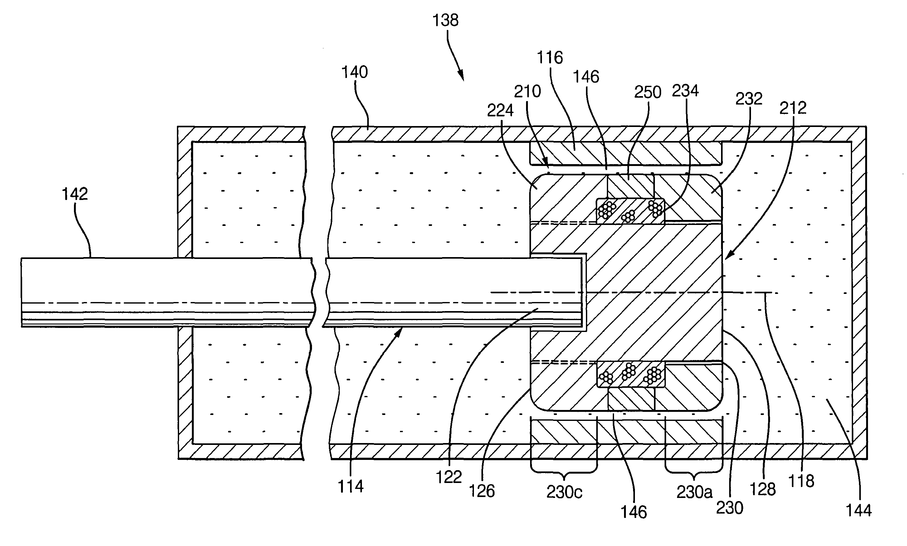
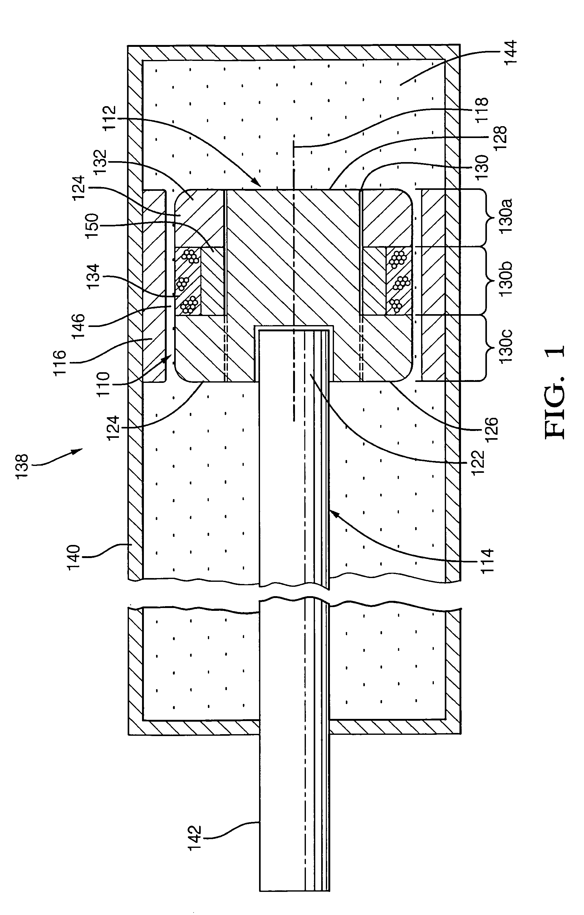
[0017]Referring now to the drawings, FIG. 1 shows an exemplary embodiment of the present invention. A magnetorheological damper 138 comprises a tube 140, piston assembly 110, and magnetorheological fluid 144. Piston assembly 110 includes piston 112, rod 114, flux ring 116, coil 134, and permanent magnet 150. The piston 112 comprises a material capable of carrying a magnetic flux. The piston has a longitudinal axis 118, a first longitudinal end 126, and a second longitudinal end 128. In one construction, the axis 118 defines an axis of symmetry about which elements are disposed in substantially cylindrical or annular fashion, but other non-circular constructions are possible. In FIG. 1, the piston 112 is shown as comprising a piston lower portion 124 and a piston upper portion 132, indicating that the piston may be made of a plurality of portions to facilitate assembly. Alternatively, suitable manufacturing techniques may be used to enable a single piece piston.

[0018]A case element a...


PUM


Abstract

A magneto-rheological damping device comprises a piston and a case element, both capable of acting to carry a magnetic flux. A passage exists between the piston and the case element, and an amount of MR fluid is positioned between the piston and the case element to flow within the passage.A first magnetic flux generator and a second magnetic flux generator cooperate to generate a net flux that is disposed to act upon the MR fluid in the passage to affect the flow of fluid in the passage.One of the flux generators comprises a permanent magnet to generate a bias flux between the piston and the case element, and the other flux generator comprises a means for providing a controllable magnetic flux between the piston and the case element.

Description

FIELD OF INVENTION[0001]This invention relates generally to magnetorheological (MR) devices and more particularly to an improved design for an MR damping device.BACKGROUND OF THE INVENTION[0002]Devices for suspending parts and controlling or damping their movement relative to one another are known in the art. For example, such devices are known and used in the automotive field in vehicle suspension systems. The devices might take the form of shock absorbers, struts, and other motion or vibration damping structures.[0003]Generally, many of those devices utilize fluids for controlling the relative movement of the mechanical parts. For example, hydraulic fluid may be utilized as a medium for creating damping forces or torques or controlling motion. One class of such movement control devices utilizes a fluid medium that is controllable through the use of magnetic fields. Such magnetically controlled fluid is referred to as magnetorheological, or MR fluid. MR fluids exhibit a thickening ...

Claims


Application Information

Patent Timeline
Patent Type & Authority Patents(United States)
IPC IPC(8): F16F9/53F16F15/03
CPCF16F9/535
Inventor NEHL, THOMAS WOLFGANGALEXANDRIDIS, ALEXANDER A.
Owner BWI CO LTD SA
Learn More