Controlling the peak levels of the FM composite signal by half-cosine interpolation

Inactive Publication Date: 2002-08-13
ORBAN ROBERT A
View PDF9 Cites 1 Cited by
  • Summary
  • Abstract
  • Description
  • Claims
  • Application Information

AI Technical Summary

Problems solved by technology

When this technology is applied to frequency modulated (FM) composite signal, unexpected difficulties arise in trying to create an FM composite clipper that is bandlimited to 53 kHz and that protects the 19 kHz pilot tone.
Filtering the clipped signal causes overshoots greater than 10% modulation and also unduly compromises the stereo separation.

Method used


Image

  • Controlling the peak levels of the FM composite signal by half-cosine interpolation
  • Controlling the peak levels of the FM composite signal by half-cosine interpolation
  • Controlling the peak levels of the FM composite signal by half-cosine interpolation

Examples


Embodiment Construction

A method for controlling the peak levels in an FM composite signal using half-cosine-interpolation is disclosed. In the following description, numerous specific details are set forth such as specific clipping depths and frequencies in order to provide a thorough understanding of the present invention. It will be apparent to one skilled in the art that the present invention may be practiced without these specific details. In other instances, well-known techniques such as clippers, samplers, and subtractors are not described in detail in order not to unnecessarily obscure the present invention.

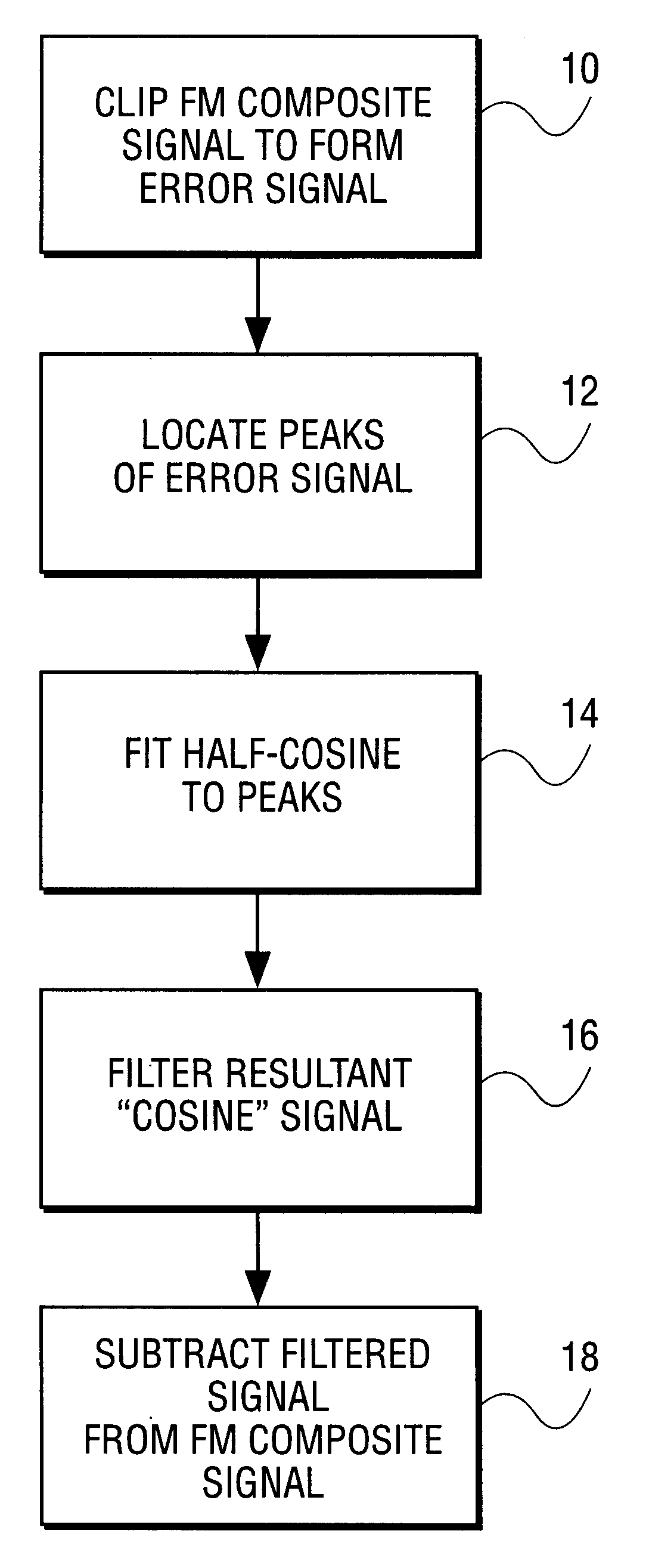
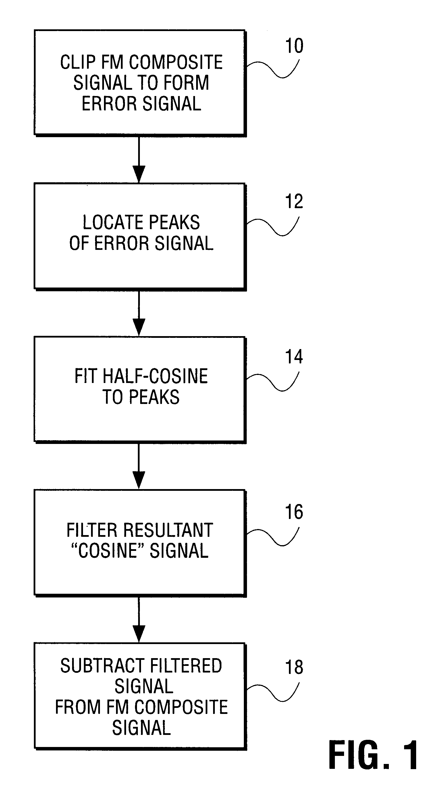
The FM composite signal is applied to a clipper to develop an error signal. This is shown as step 10 in FIG. 1. The error signal is that part of the waveform that is removed by the clipper, the "clippings". The error signal typically consists of a number of spikes, which are likely to be "sliced" segments of the 38 kHz stereo subcarrier.

Now the peaks of the error signal are found as shown by ste...


PUM


Abstract

A method for controlling the peak levels of an FM composite signal is described. First, the FM signal is clipped to obtain an error signal. This signal comprises the "clippings" resulting from the clipping operation. Next, the peaks of the error signal are determined. Then, a half-cosine wave is fitted to each of the peaks. The resultant half-cosine-interpolated signal is filtered to provide a filtered error signal. This error signal is subtracted from the FM composite signal.

Description

1. Field of the InventionThe invention relates to the field of controlling peak levels of frequency modulated (FM) signals.2. Prior ArtAudio signals are frequently clipped at predetermined thresholds particularly in the broadcast field to prevent over-modulation of the transmitter, which is ordinarily defined by government regulations. In many instances, the "clippings" are used in subsequent processing. The use of "clippings" for signal processing is described in U.S. Pat. No. 5,737,434 entitled "Multi-Band Audio Compressor with Look-Ahead Clipper" and U.S. patent application Ser. No. 09 / 216,345, filed Dec. 18, 1998, entitled "Oversampled Differential Clipper," assigned to the Assignee of the present invention.When this technology is applied to frequency modulated (FM) composite signal, unexpected difficulties arise in trying to create an FM composite clipper that is bandlimited to 53 kHz and that protects the 19 kHz pilot tone. Filtering the clipped signal causes overshoots greate...

Claims


Application Information

Patent Timeline
IPC IPC(8): H03G11/00H04H1/00H04H40/36
CPCH03G11/008H04H40/36
Inventor ORBAN, ROBERT A.
Owner ORBAN ROBERT A
Why Eureka
Try Eureka