Device arranged to permit an air flow from an environment to an inner space

a technology of an environment and an airflow, which is applied in the direction of milking devices, mechanical devices, functional valve types, etc., can solve the problems of air inlets, muck, insect legs or dried milk, and the opening will finally be completely closed

Inactive Publication Date: 2002-08-27
DELAVAL HLDG AB
View PDF16 Cites 9 Cited by
  • Summary
  • Abstract
  • Description
  • Claims
  • Application Information

AI Technical Summary

Problems solved by technology

However, such air inlets have the drawback that they often become filled up with dirt, muck, insect legs or dried milk.
It thereby happens that a fly gets stuck with a leg in the air inlet opening, which results in that the opening will finally be completely closed.
In addition to the risk of being filled up, such relatively small openings are difficult and expensive to produce in for example a teat cup claw of steel but it is also difficult to make such a small opening in a teat cup claw of plastic, since the opening is very small in relation to the teat cup claw.
Consequently, the convex surface area, with the passage, will not be so attractive for flies and other insects.

Method used


Image

  • Device arranged to permit an air flow from an environment to an inner space
  • Device arranged to permit an air flow from an environment to an inner space
  • Device arranged to permit an air flow from an environment to an inner space

Examples


Embodiment Construction

The invention is now to be shown in different embodiments where the device according to the invention has been applied to different milking members.

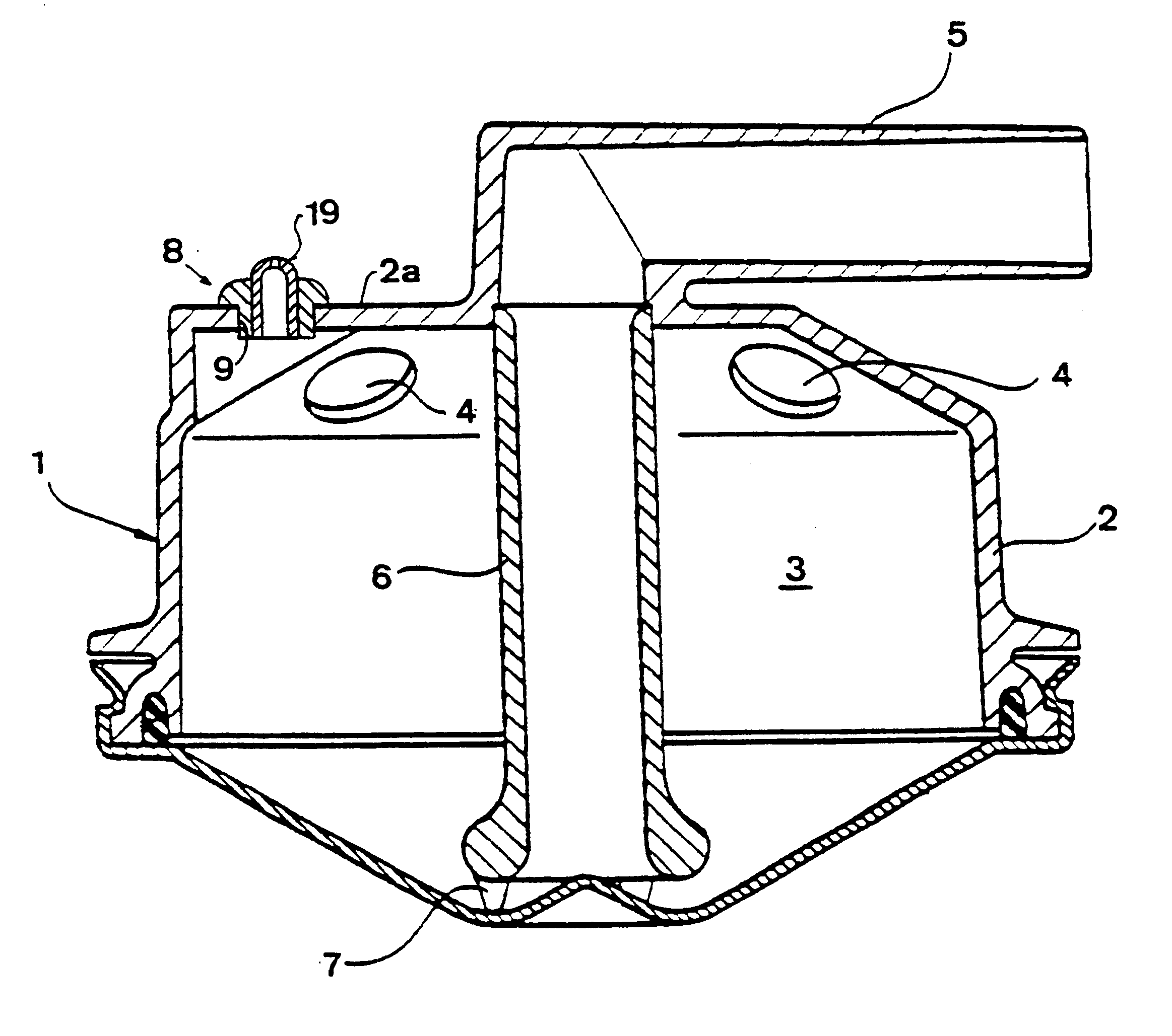
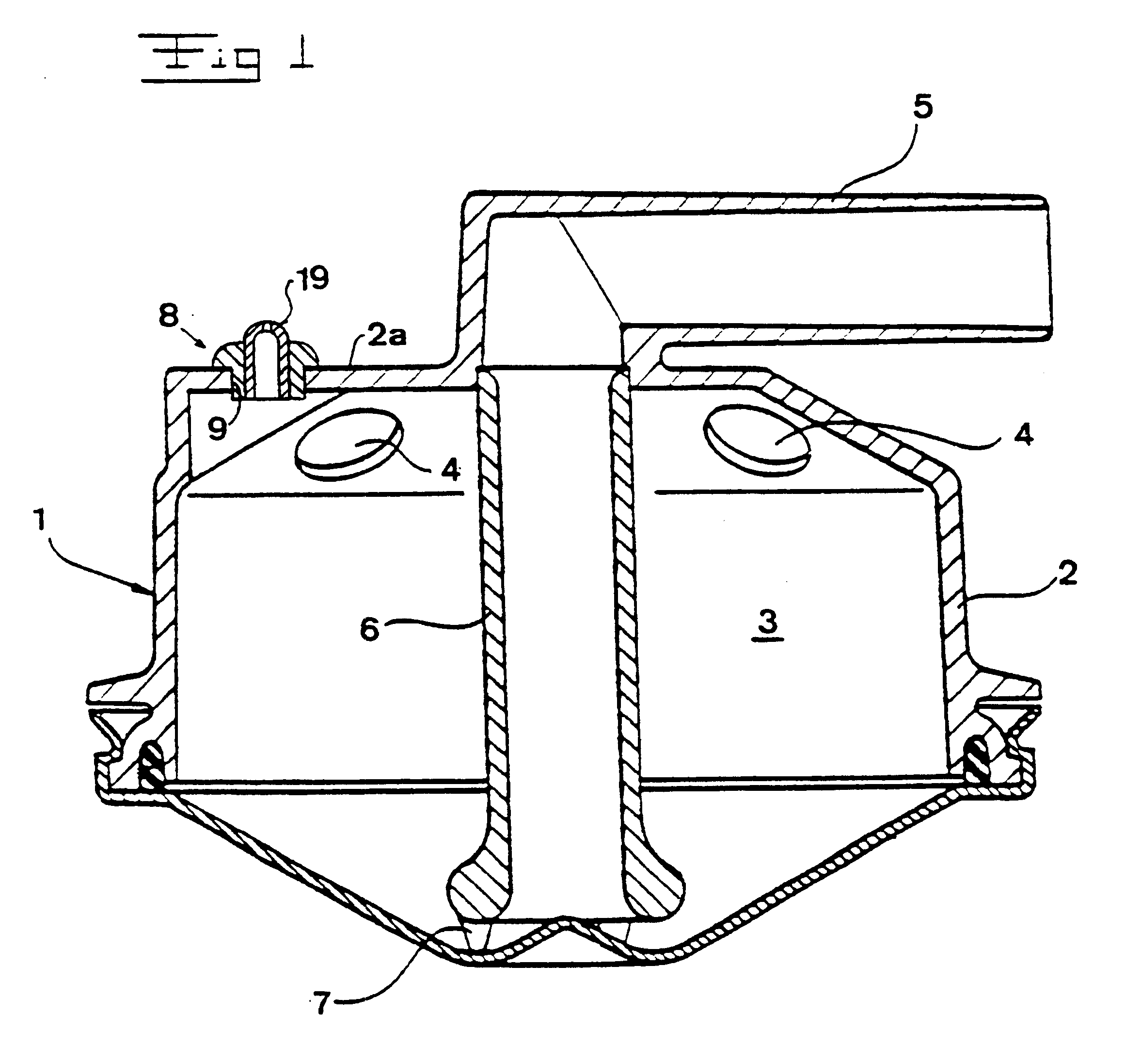
FIG. 1 shows a vertical cross-sectional view through a teat cup claw 1, which comprises a casing or a wall 2, which encloses an inner space 3. in an upper portion of the wall there are four inlet openings 4, of which two are shown in FIG. 1 and each of which is arranged to receive a short milk duct, which extends to a teat cup (not shown). Consequently, the teat cup claw 1 is arranged to receive the milk, which is produced in connection with milking, through the inlet openings 4. Furthermore, the teat cup claw 1 comprises an outlet tube 5, which via a long milk duct (not shown) is connected to a vacuum pump of a milking machine. Consequently, the milk, which is accumulated in the inner space 3 of the teat cup claw 1, is sucked out of the latter through the outlet tube 5 via a suction tube 6, which rests on the bottom of the teat cup claw...


PUM


Abstract

The invention refers to a device (8) which is arranged to permit an air flow from an environment to an inner space (3) of a member (1). The device (8) comprises a passage through a wall section (2a) of said member (1). The wall section (2a) comprises a convex surface area (19) which faces said environment, wherein the passage extends through the surface area (19). In one application of the invention said member comprises a milking member (1).

Description

THE BACKGROUND OF THE INVENTION AND PRIOR ART1. Field of the InventionThe present invention concerns a device arranged to permit an air flow from an environment to an inner space of a member, comprising a passage through a wall section of said member.2. Description of the Prior ArtIt is known to provide such air inlet devices in connection with milking members. For example U.S. Pat. No. 5,076,211 shows a teat cup claw with such an air inlet formed by a simple opening, which extends through a wall section of the teat cup claw. The object by such an air inlet is to create a flow through an inner space of the teat cup claw which inner space is connected to a vacuum pump in order to enable transportation of the milk, which is present in the inner space. At the same time, it is desirable to mix as little air as possible with the milk in order to be able to maintain a high quality of the latter. That means that the opening is to be made small, i.e. with a small diameter which usually may ...

Claims


Application Information

Patent Timeline
Patent Type & Authority Patents(United States)
IPC IPC(8): A01J5/00A01J5/04F16K24/00F16K24/06F16K47/00A01J7/00
CPCA01J5/041F16K24/06
Inventor PETTERSON, TORBJORN KARL INGEMAR
Owner DELAVAL HLDG AB
Why Eureka
Try Eureka