Electrical connector with releasable pick-up device

Inactive Publication Date: 2002-08-27
HON HAI PRECISION IND CO LTD
View PDF4 Cites 58 Cited by
  • Summary
  • Abstract
  • Description
  • Claims
  • Application Information

AI Technical Summary

Benefits of technology

Another object of the present invention is to provide an electrical connector with a rel

Problems solved by technology

However, when the cap member is press-fitted into or is pulled out from the mating cavity of th

Method used


Image

  • Electrical connector with releasable pick-up device
  • Electrical connector with releasable pick-up device
  • Electrical connector with releasable pick-up device

Examples


Example

Reference will now be made to the drawing figures to describe the present invention in detail.

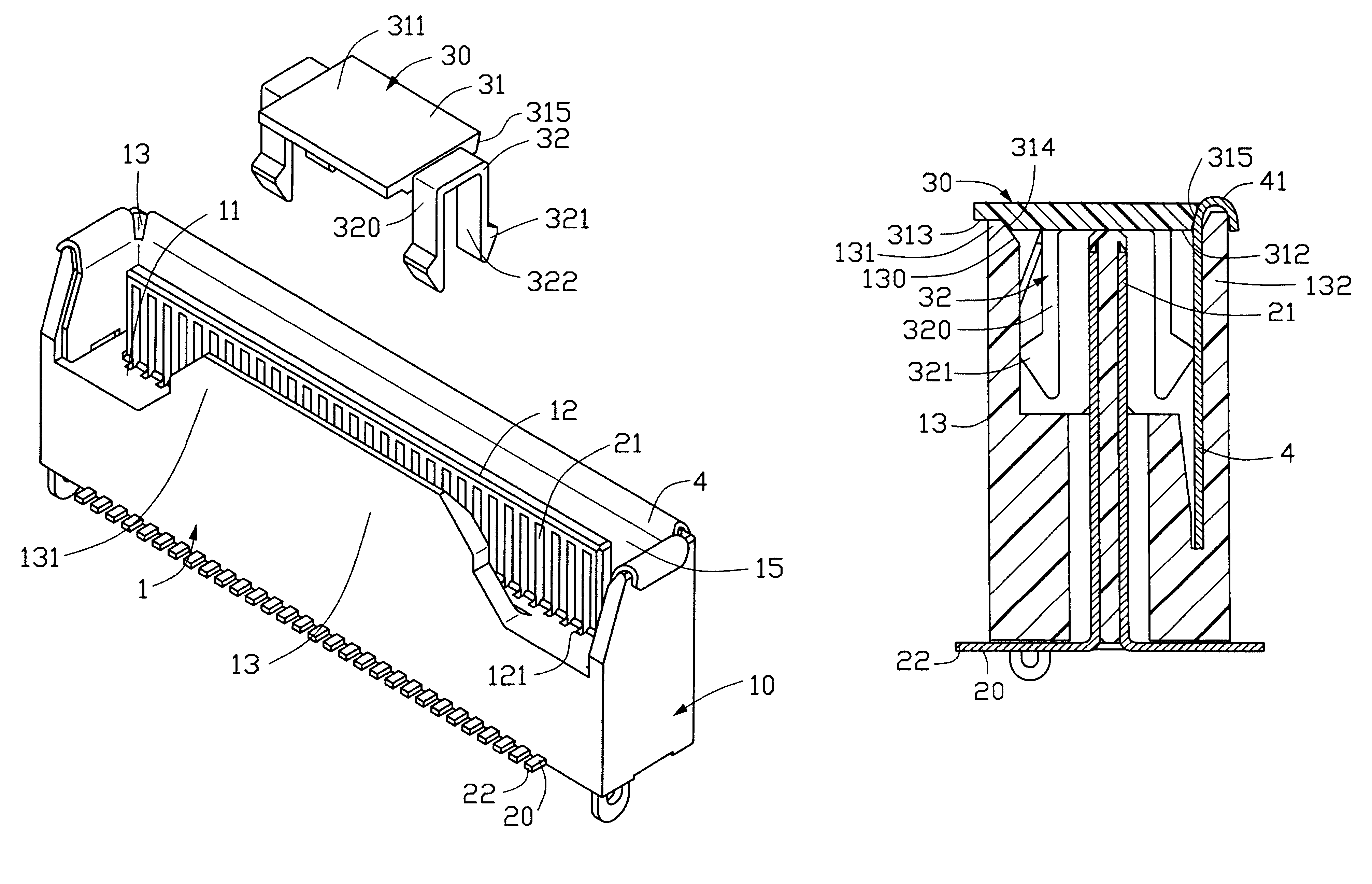
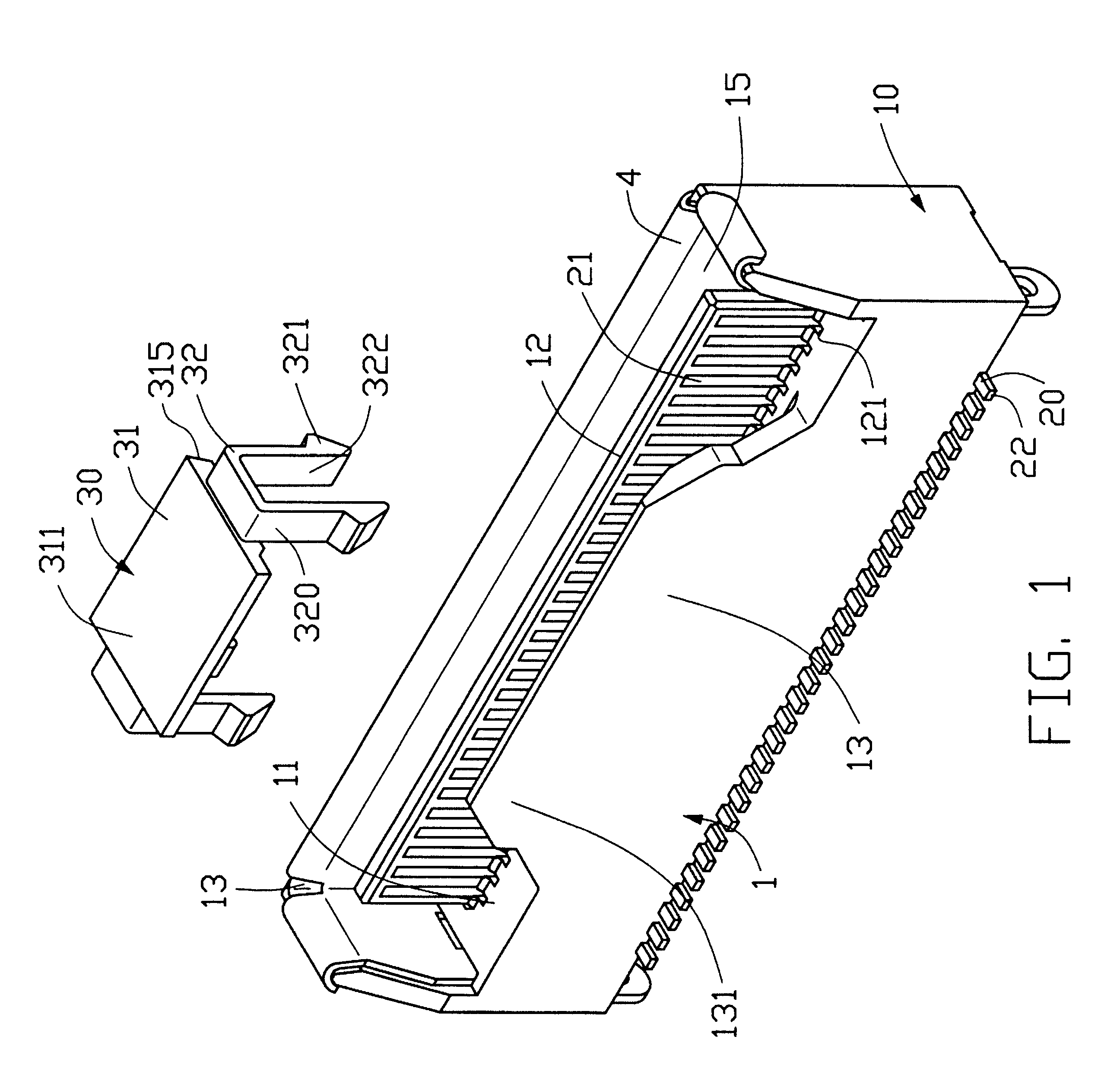
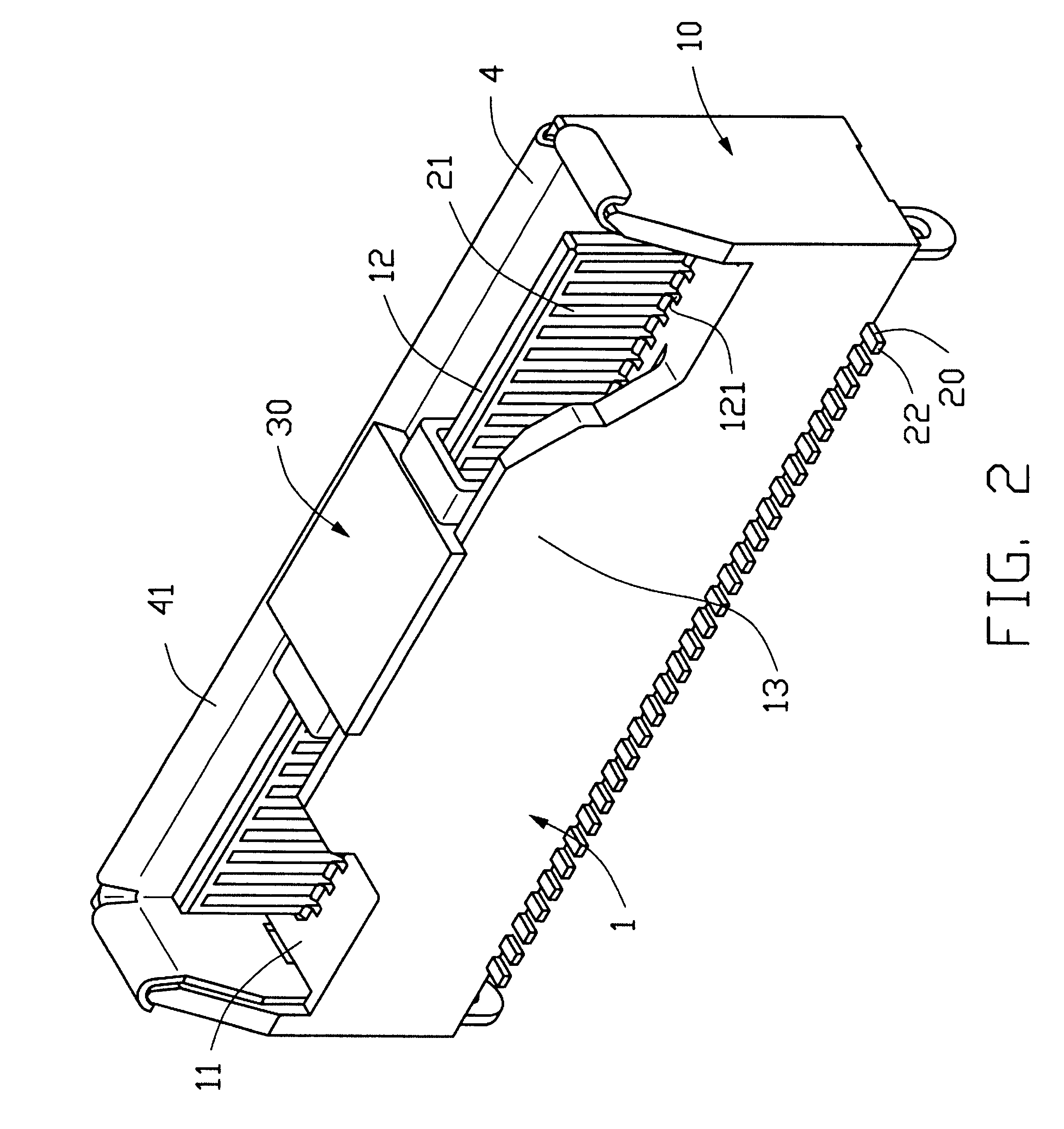
Referring to FIGS. 1 through 4, a pick-up device 30 made of resilient insulating material in accordance with the present invention, attachable to an electrical connector 1, comprises a rectangular plate 31 and a pair of U-shaped retaining portions 32 extending from opposite transverse side edges of the rectangular plate 31. Each U-shaped retaining portion 32 comprises a pair of downwardly projecting legs 320, between which an engaging space 322 is defined. Retaining feet 321 are formed respectively on outer surfaces of the pair of legs 320 at lower ends and protrude in directions opposite to each other. The rectangular plate 31 has a flat, upper surface 311 for suction by a vacuum-suction nozzle and a lower surface 312 opposite to the upper surface 311. A longitudinally depressed area 313 is defined in the lower surface 312. Between the depressed area 313 and the lower surface 312, an incli...


PUM


Abstract

A releasable pick-up device (30) for assisting in positioning an electrical connector (1) on a circuit board by a vacuum-suction nozzle, comprises a rectangular plate (31) having a flat upper surface (311) to be manipulated by the nozzle and an opposite lower surface (312), and a pair of retaining portions (32) extending from opposite transverse sides of the plate. Each retaining portion forms a pair of downwardly projecting legs (320) having a pair of respective retaining feet (321) formed at free ends thereof and protruding in directions opposite to each other.

Description

BACKGROUND OF THE INVENTION1. Field of the InventionThe present invention relates to an electrical connector to be placed on a surface of a circuit board by a conventional, vacuum-suction tool, and particularly to a surface mount electrical connector with a releasable pick-up device.2. Description of Related ArtIn order to answer for the requirement of automatic operation, the use of vacuum-suction tools to pick up and place electrical connectors or other electrical articles on circuit boards is well known in the art. The related art, referring to U.S. Pat. No. 5,249,977, discloses a conventional plug connector having a cap member releasably attached thereto for carrying to a circuit board by a vacuum-suction tool so as to implement soldering procedure. The conventional plug connector has an elongate mating cavity opening to a mating face and a mating rib projecting, centrally of the mating cavity, from a base wall of the connector. The mating rib defines a plurality of passageways ...

Claims


Application Information

Patent Timeline
IPC IPC(8): H01R43/20H05K13/04
CPCH01R43/205H05K13/04Y10S439/94
Inventor JI, ZHANG JIANGCHENG, WEI YA
Owner HON HAI PRECISION IND CO LTD
Why Eureka
Try Eureka