Tape cartridge with matched brake lock and brake release plate

a technology of brake lock and release plate, which is applied in the field of single-reel tape cartridges, can solve the problems of affecting the smooth turning of the tape reel, the idea has not yet materialized in a perfect solution,

Inactive Publication Date: 2002-09-17
TDK CORPARATION
View PDF15 Cites 37 Cited by
  • Summary
  • Abstract
  • Description
  • Claims
  • Application Information

AI Technical Summary

Problems solved by technology

However, the idea has not yet materialized in a perfect solution.
If the two parts

Method used


Image

  • Tape cartridge with matched brake lock and brake release plate
  • Tape cartridge with matched brake lock and brake release plate
  • Tape cartridge with matched brake lock and brake release plate

Examples


first embodiment

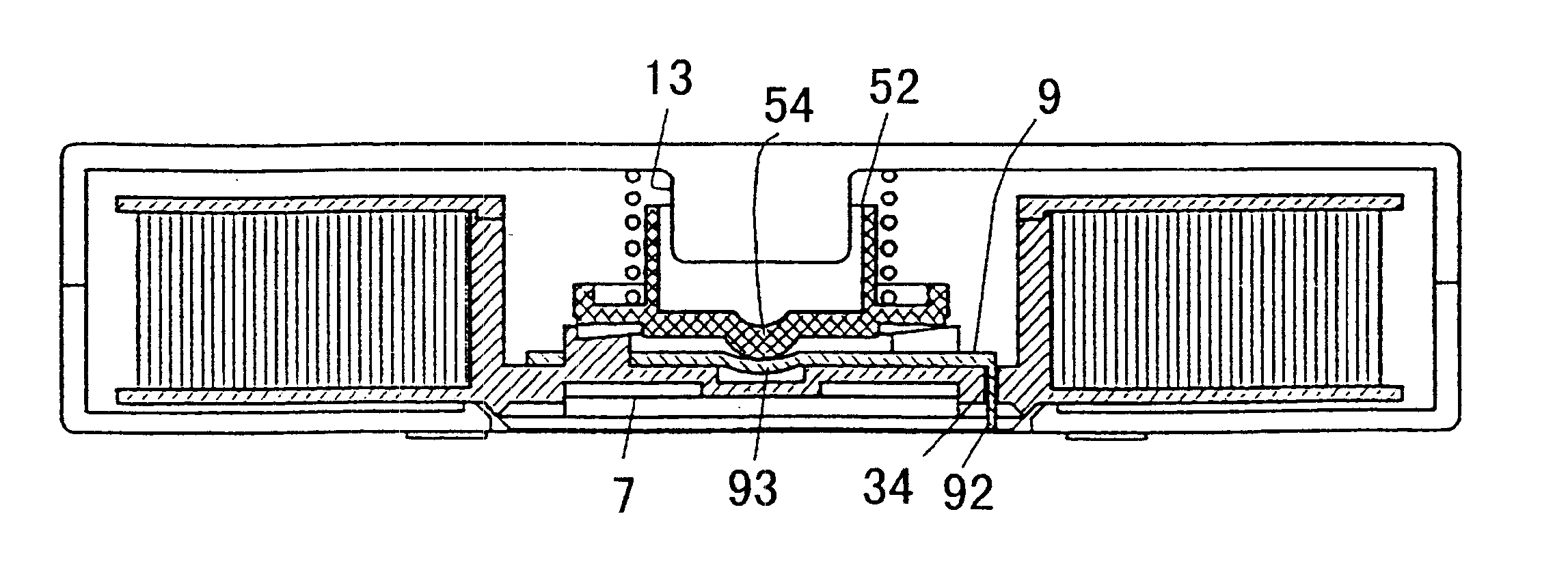
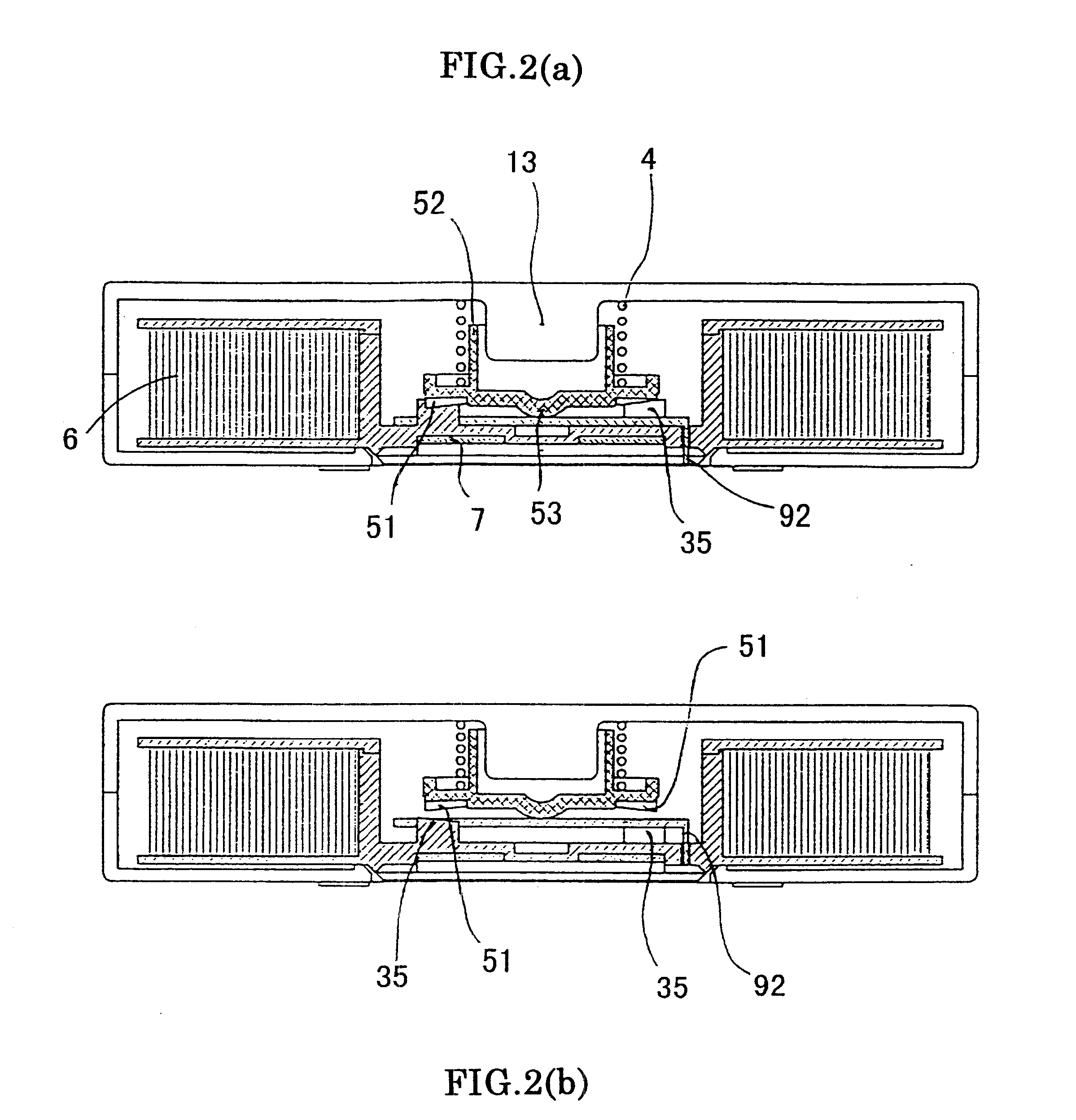
Under the invention, as shown in FIG. 3, a lug 54 is formed in the center of brake lock 5 and a dent 93 in the center of the main plate 91 of brake release plate 9. Thus, even if brake lock 5 and brake release plate 9 are out of center alignment upon release of the brake, the concave and convex of the two centers remain aligned, ensuring stable turning of the tape reel. The alignment is made more certain by forming a dent 93 with a radius of curvature R greater than the radius r of the convex surface of lug 53.

second embodiment

FIG. 4 illustrates reversal of the concavo-convex relationship. Lug 54 of the first embodiment is replaced by a dent 55 and dent 93 replaced by a lug 94, and a similar favorable effect is achieved. Dent 55 with a radius of curvature R greater than the radius 5 of the head of lug 94 enhances the alignment.

Even when the center of either brake release plate or brake lock is off the center of the other, the two centers can be aligned and stable tape running is ensured.

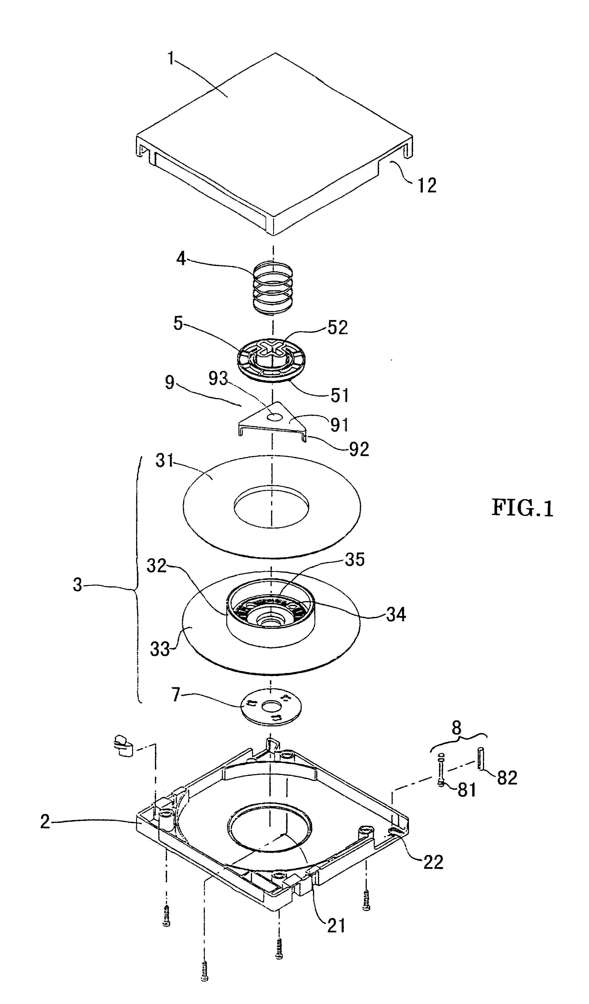
FIG. 7 is an exploded view of a tape cartridge as another embodiment of the invention.

The cartridge comprises a housing consisting of upper and lower casings 1, 2 and a single tape reel 3 on which a length of tape is wound and which is turnably contained in the housing.

Lower casing 2 has an opening 21 through which a drive shaft of a recorder is inserted into the housing. Upper and lower casings 1, 2 have cutouts 12, 22, respectively, which are joined to form an opening through which tape is to be pulled out.

Tape reel 3 co...


PUM


Abstract

In a tape cartridge of the single-reel type having a hub on which a length of tape is wound, a brake mechanism contained in the hub is movable up and down to apply and release the brake on the tape reel. The brake mechanism and a brake lock release member disposed between it and the hub remain in sliding engagement after the release of the brake, and the resulting friction hampers smooth turning of the hub. Moreover, after the brake lock has been released, the center of the tape reel can be off the center of a rotating shaft of a recorder.The hub of the tape reel has holes formed in its bottom wall for engagement with the brake release plate, the brake release plate is mounted in the hub with legs fitted in the holes of the latter, the brake lock rests on the brake release plate, the brake lock is formed with a dent (or lug) with a spherical end and the brake release plate is formed with a corresponding lug (or dent) with a spherical end on its upper surface. A highly slippery sheet member is interposed between the contacting parts of the brake lock and the brake release plate.

Description

1. Field of the InventionThis invention relates to a single-reel type tape cartridge for use with magnetic recording-reproducing apparatus (hereinafter called a "recorder").2. Prior ArtJapanese Patent Application Kokai No. 63-251983 discloses a single-reel type tape cartridge having a brake lock which applies the brake on the tape reel and releases it by upward and downward motion within a hub on which the tape is wound.FIG. 5 is an exploded view of a single-reel type cartridge of the prior art and FIG. 6 is a cross sectional view showing essential parts of the cartridge. For easier reference the components are shown upside down. The cartridge comprises a housing composed of an upper casing 1 and a lower casing 2, and a single tape reel 3 on which a length of tape 14 is wound and which is turnably held within the housing.Upper and lower casings 1, 2 are formed, respectively, with cutouts 12, 22 which are joined to provide an opening into which a leader block 9 is inserted so as to b...

Claims


Application Information

Patent Timeline
IPC IPC(8): G11B23/107G11B23/04G11B23/08
CPCG11B23/043G11B23/107
Inventor SHIMA, MOTOHIKOKANEDA, HIROSHIOKAMURA, MASATOSHI
Owner TDK CORPARATION
Why Eureka
Try Eureka