Angle portion of an endoscope

a technology of endoscope and angular joint tube, which is applied in the field of endoscope insertion instruments, can solve the problems of difficult to move the operating wires 15 smoothly, difficult to locate, and very likely to interfere between these component parts

Inactive Publication Date: 2002-09-24
FUJI PHOTO OPTICAL CO LTD
View PDF7 Cites 32 Cited by
  • Summary
  • Abstract
  • Description
  • Claims
  • Application Information

AI Technical Summary

Problems solved by technology

However, if the respective components are located in most desirable positions form the standpoint of endoscopic operation, interferences are very likely to occur between these component parts and the lancing arches 17 or the soldered connections 18.
Therefore, when laying out the instrument projecting outlet 6 and illumination windows 4 on the basis of a position of the observation window 5, difficulties are usually encountered in locating these parts in most suitable positions.
However, if the positions of the lancing arches 17 are shifted, the operating wires 15 are bent angularly between the foremost wire guides 16 and the lancing arches 17 and therefore are subjected to larger friction forces within the wire guides 16 each time when the wires 15 in a slackened state are pulled into a tensioned state for an angling operation, making it difficult to move the operating wires 15 smoothly in addition to increased possibilities of damages to the wires 15.
However, an increase of that distance is inevitably reflected by an increase in length of the rigid portion at the distal end of the insert rod portion 2, which makes it difficult to introduce the endoscope smoothly into a body cavity smoothly and without arousing much pains on the part of a patient.

Method used


Image

  • Angle portion of an endoscope
  • Angle portion of an endoscope
  • Angle portion of an endoscope

Examples


Embodiment Construction

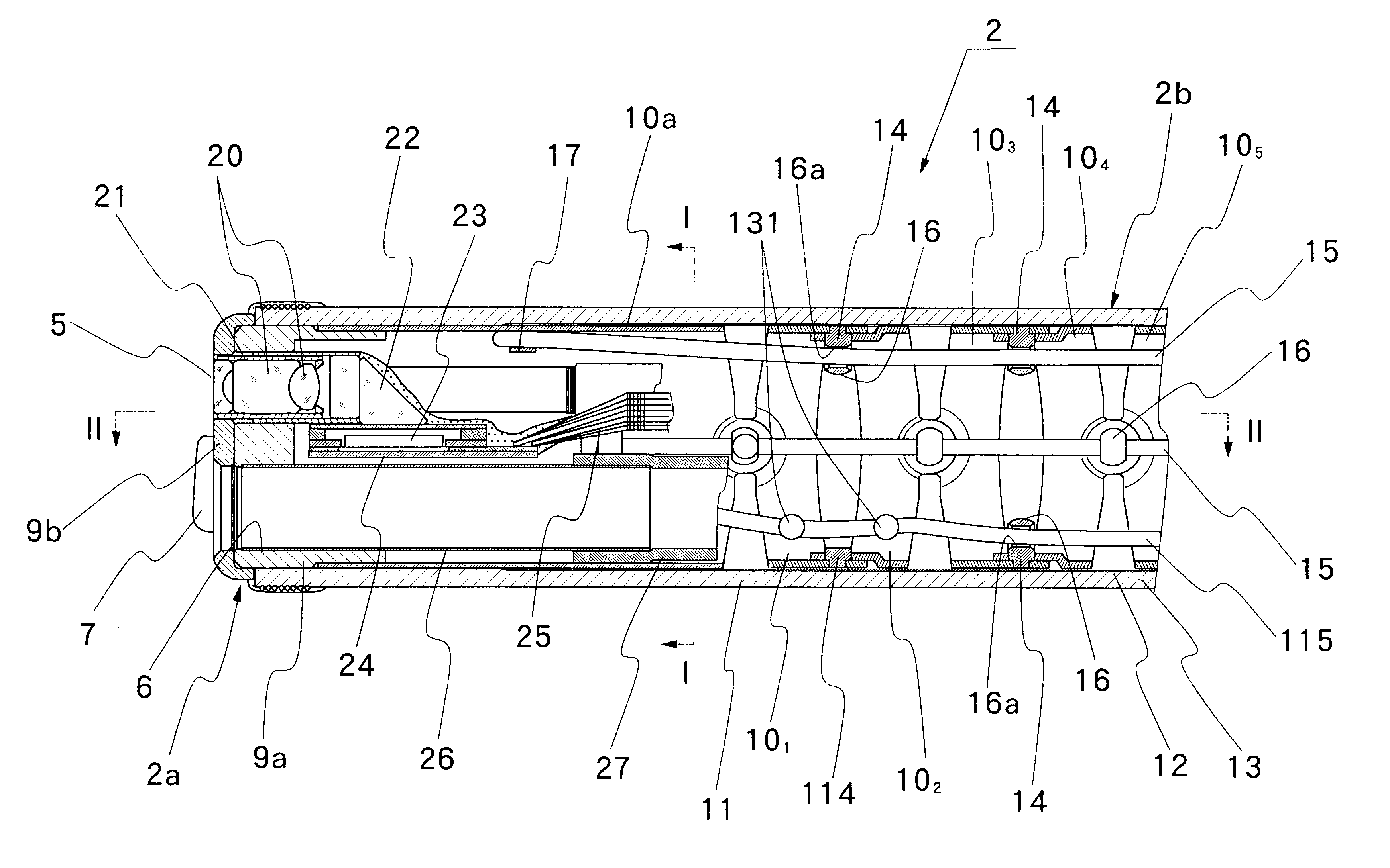
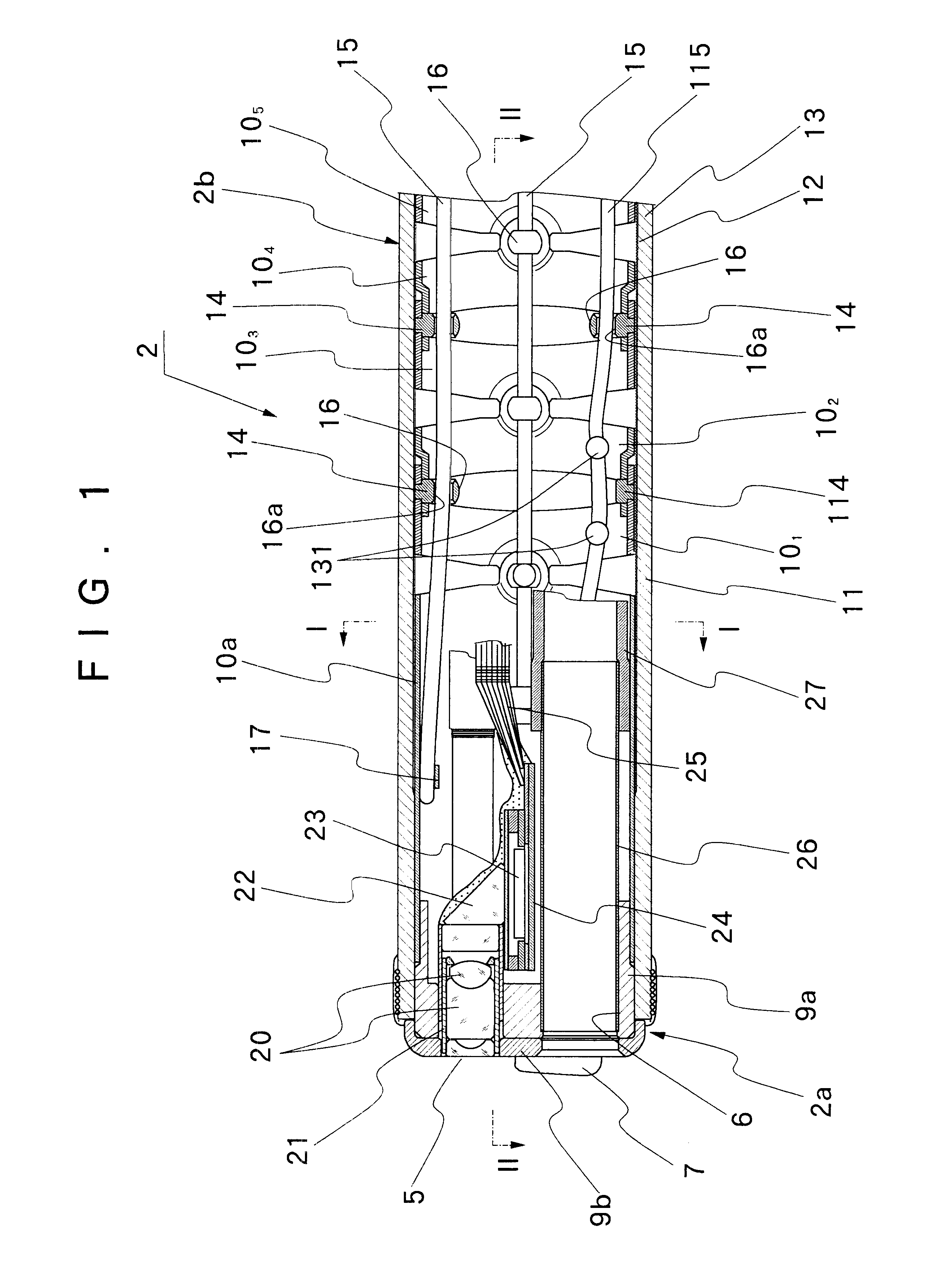
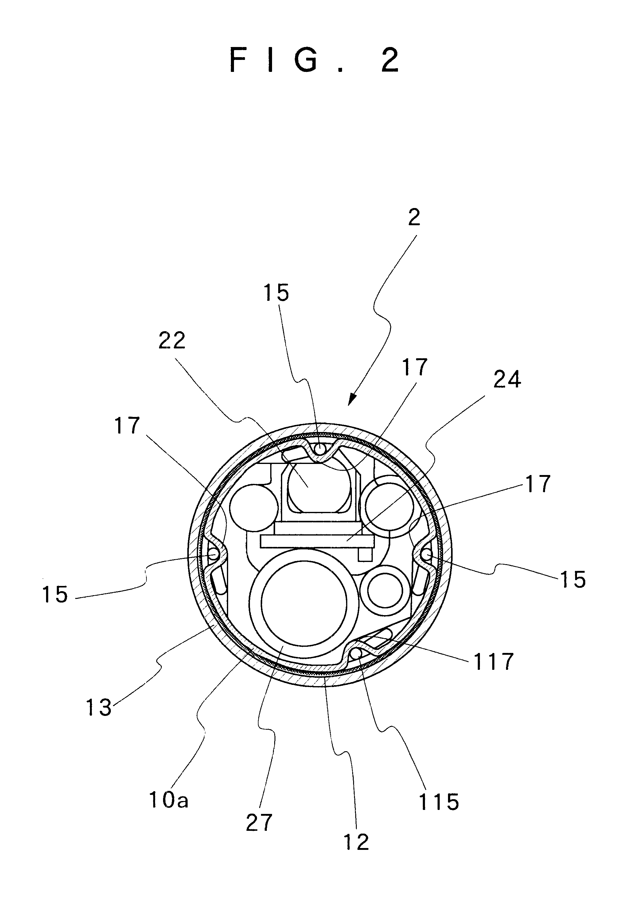
Hereafter, the present invention is described more particularly by way of its preferred embodiment shown in the accompanying drawings. In the following description of a preferred embodiment which has no differences in particular from the above-described prior art in basic layout of component parts except layout of a path or paths of an operating wire or wires in the angle portion of the endoscope, those component parts which are equivalent or identical with the counterparts in the above-described prior art are designated by similar reference numerals or characters to avoid repetitions of same explanations.

As shown in FIGS. 1 and 2, from the standpoint of maneuverability of the endoscope and of biopsy or surgical instruments, a center line of a view field through the observation window 5 on the rigid tip end section 2a should desirably be located on or close to a center line of vertical or upward and downward bending movements, while the instrument projecting outlet 6 should desirabl...


PUM


Abstract

Within a flexible angling joint tube which is connected to a rigid tip end section of an endoscopic insertion instrument and which is formed by connecting a predetermined number of angle rings successively and pivotally by the use of pivoting pins, a plural number of operating wires are passed in an axial direction via the respective pivoting pins. Fore ends of the operating wires are fixedly anchored at fixation points in boundary portions of the rigid tip end section and the flexible angling joint tube. An operating wire fixation point for at least one operating wire is shifted to an angular position in the circumferential direction from a normal position on an axial extension line from a row of pivoting pins. A wire guide pin is fixedly provided at least one of angle rings which are connected by the foremost pivoting pins to guide the one operating wire in such a way as to evade at least a top portion of the foremost pivoting pin as the one operating wire is pulled or pushed in the axial direction to bend the angling joint tube.

Description

1. Field of the ArtThis invention relates generally to endoscopic insertion instruments for medical use, and more particularly to a flexibly bendable, angling joint tube for use as an angle portion of endoscopic insertion instruments.2. Prior ArtFirstly, illustrated in FIG. 8 is a general layout of a typical endoscopic insertion instrument in use in medical fields. The endoscopic insertion instrument is largely constituted by a manipulating head assembly 1, a rod-like insert member 2 which is extended out on the front side of the manipulating head assembly 1 for insertion into a body cavity, and a universal cable 3 which is led out on the rear side of the manipulating head assembly 1 for connection to a light source. The insert member 2 comprises at least a rigid tip end section 2a which is internally provided with an observation means, an angle section 2b which is connected to the proximal end of the rigid tip end section 2a, and a lengthy flexible body section 2c which extends fro...

Claims


Application Information

Patent Timeline
Patent Type & Authority Patents(United States)
IPC IPC(8): A61B1/005A61B1/00G02B23/24
CPCA61B1/0055A61B1/0057
Inventor IDE, MASAO
Owner FUJI PHOTO OPTICAL CO LTD
Why Eureka
Try Eureka