Virtual camera control method in three-dimensional video game

a virtual camera and video game technology, applied in the field of virtual camera control methods in three-dimensional video games, can solve the problems of monotonous change in the display screen, inability to establish a battle in an rpg, and inability to change the display screen monotonously

Active Publication Date: 2004-09-09
SQUARE ENIX HLDG CO LTD
View PDF9 Cites 45 Cited by
  • Summary
  • Abstract
  • Description
  • Claims
  • Application Information

AI Technical Summary

Benefits of technology

[0018] As explained above, the viewpoint position evaluator evaluates each temporary viewpoint position based on the angle formed by the straight line connecting the current viewpoint position of the virtual camera to the calculated central position and each straight line connecting each of the multiple temporary points to the central position, thereby allowing a reduction in an amount of movement of the viewpoint. By the reduction in the amount of movement, no feeling that something is wrong occurs when changing the displayed screen. The viewpoint position evaluator evaluates each temporary viewpoint position based on the overlap degree of the characters, thereby making it easy to view the characters on the displayed screen. The viewpoint position evaluator evaluates each temporary viewpoint position according to the height difference between the characters, thereby making it easy for the player to recognize the size of the characters on the displayed screen.

Problems solved by technology

The image projected from the same position was repeatedly displayed on the display screen, so that a change in the display screen becomes monotonous.
This technique cannot solve the problem that a change in the display screen becomes monotonous.
On the contrary, the battle in an RPG cannot be established unless at least two characters including one player character and one enemy character exist.
However, there is a problem that each character may be displayed small or the characters may be displayed on one-side according to the position where the character moved.

Method used


Image

  • Virtual camera control method in three-dimensional video game
  • Virtual camera control method in three-dimensional video game
  • Virtual camera control method in three-dimensional video game

Examples


Embodiment Construction

[0036] An embodiment of the present invention will be specifically described with reference to the drawings.

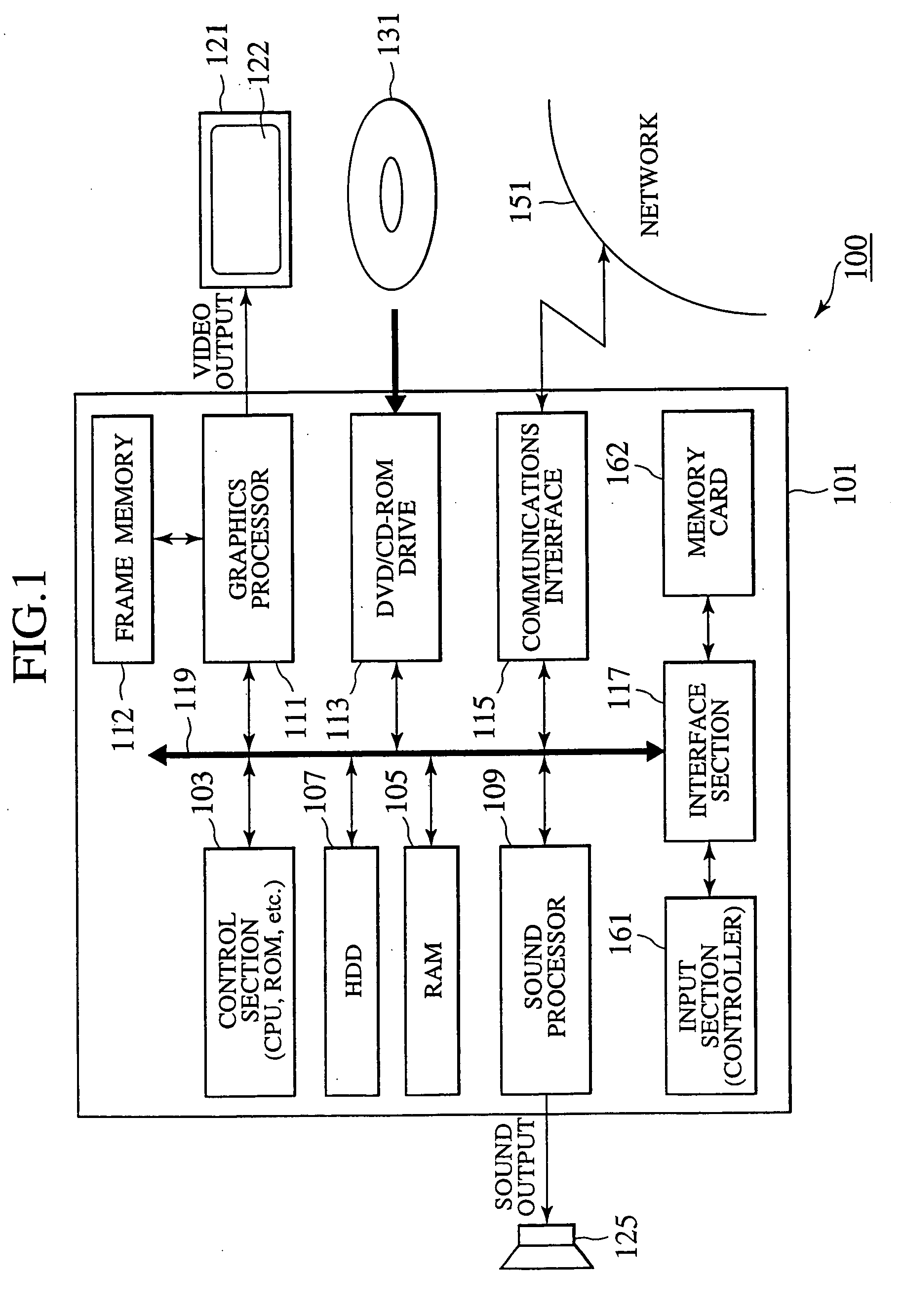
[0037] FIG. 1 is a block diagram illustrating a configuration of a video game apparatus 100 for executing a three-dimensional game according to this embodiment. As illustrated in the figure, a video game apparatus 100 includes a video game main body 101. The video game main body 101 includes a control section 103, a RAM (Random Access Memory) 105, a hard disk drive (HDD) 107, a sound processor 109, a graphics processor 111, a DVD / CD-ROM drive 113, a communications interface 115, and an interface section 117. The control section 103, the RAM 105, the HDD 107, the sound processor 109, the graphics processor 111, the DVD / CD-ROM drive 113, the communications interface 115, and the interface section 117 are connected to an internal bus 119.

[0038] The sound processor 109 of the video game main body 101 is connected to a sound output device 125, which is a speaker, and the graphics p...


PUM


Abstract

A central position of each character participating in a battle is obtained as a fixation point, and multiple temporary points are set on a hemisphere around the fixation point. Each temporary viewpoint position is set on a straight line connecting the fixation point to each temporary point. Each temporary viewpoint position is a position from which all characters can be projected on a virtual screen when perspective transformation is executed at a predetermined visual angle and a distance to the fixation point is shortest. Points are given to each temporary viewpoint position based on the result of a distance evaluation, an angle evaluation, an overlap evaluation, and a height difference evaluation. The top scoring temporary viewpoint positions are selected as positions where the viewpoint of a virtual camera should be moved.

Description

[0001] The present disclosure relates to subject matter contained in Japanese Patent Application No. 2003-58136, filed on Mar. 5, 2003, the disclosure of which is expressly incorporated herein by reference in its entirety.[0002] 1. Field of the Invention[0003] The present invention relates to a technique that determines a viewpoint position of a virtual camera when multiple characters exist in a virtual three-dimensional space in a three-dimensional video game.[0004] 2. Description of the Related Art[0005] In a role playing game (RPG), a battle between player characters and enemy characters is generally performed in the process of the game. In the case of a three-dimensional video game, the state of the battle is perspective-transformed by a virtual camera provided on a battle field (battle map) and displayed on a display screen. A player can recognize the state of the game from only an image on the display screen.[0006] In the conventional RPG, the image displayed on the display sc...

Claims


Application Information

Patent Timeline
Patent Type & Authority Applications(United States)
IPC IPC(8): A63F13/55A63F13/45A63F13/5258A63F13/822
CPCA63F13/10A63F2300/64A63F2300/807A63F2300/8029A63F2300/6661A63F13/45A63F13/5255A63F13/822
Inventor KOBAYASHI, KAZUMI
Owner SQUARE ENIX HLDG CO LTD
Why Eureka
Try Eureka