Methods of operating arrangements of base transceiver stations in an area-covering network

a technology of area-covering network and operating arrangement, applied in the direction of transmission, substation equipment, wireless communication, etc., can solve the problems of significantly increasing the cost of the radio network, high investment required for conventional base transceiver stations, and large aerial and installation costs

Inactive Publication Date: 2002-10-01
LITTLEFEET
View PDF70 Cites 77 Cited by
  • Summary
  • Abstract
  • Description
  • Claims
  • Application Information

AI Technical Summary

Benefits of technology

It has proved advantageous if the decentral cell area(s) as a whole completely surround the central cell(s). This ensures on the one hand an arrangement with an optimum coverage area, which may be approximately four to ten times as large as the original or central cell area. Thus the number of base stations coupled to a base station controller is reduced by a corresponding factor. On the other hand, the central cell area is completely surrounded by the decentral cell areas, so that the transmission frequencies of the central cell(s) can already be used in the adjacent transceiver station coupled to a base station controller.
It has been found advantageous if the switch is opened by the reception field strength detector when the signal is below a further threshold value. If this second threshold value is below the first threshold value, a hysteresis is obtained which ensures stable operation even at the periphery of a cell.

Problems solved by technology

On the other hand, any conventional base transceiver station requires a high level of investment, which considerably increases the cost of the radio network.
It has been proposed in the prior art to provide at each base transceiver station, instead of one non-directional aerial, three directional aerials, each covering a transmission or reception angle of approximately 120.degree., so that the number of cells can be tripled, but such a modus operandi involves heavily increased aerial and installation costs.
On the other hand, however, the total number of frequencies should not be increased, since the transmission frequencies available are limited by a number of other data transmission systems.
This reduces the initial investment.
Here the problem arises of finding a suitable structure in which if possible all the sites of existing base transceiver stations can be reused, and investment in additional installations at new sites will be kept as low as possible.
Furthermore, however, a weakened signal is received by the other transceiver stations of this cell area and is transmitted to the central transceiver station.
This makes the costly, labour-intensive laying of a coupling cable between the mutually remote base transceiver stations superfluous.
The installation of such a decentral transceiver station is therefore extremely labour-saving.
In the arrangement described above, it may prove disadvantageous if the base transceiver stations coupled to the base station controller have their own cell which is surrounded by further cell areas.
This means that, in addition to the frequencies required for the outer cell areas, further, different frequencies are required for the central cells, so that although the above arrangement is an improvement over the prior art, on the whole it is not the best solution.
In cell areas with only one central transmission aerial, on the other hand, the interference is so great that its use hitherto has only been practical if the frequencies were repeated, not even in the next-but-one cell area, but at greater distances, so that a large number of different transmission frequencies were necessary.
This makes it possible to install the individual transceiver stations at the optimum site for one cell area, so that the search for a site is generally unproblematic.
In particularly unfavourable cases, where it is not possible to install the transceiver station at a desired site, by way of compensation one or more extra transceiver stations can be inserted in order to fill up any gaps in the radio network.
In the prior art, this was only possible at great cost with only one transceiver station per cell area, since an extra transceiver station with its own transmission frequencies was required, which necessitated a complete change in the geometry of the network.
In particular in cell areas more remote from the associated central station effecting coupling to a base station controller, the problem arises that the different transceiver stations of this cell area may have different distances from the associated connection station.
Thus running time differences can arise, which within the cell area would lead to asynchronous transmission so that, for example, the desired amplifying effect is not achieved.

Method used


Image

  • Methods of operating arrangements of base transceiver stations in an area-covering network
  • Methods of operating arrangements of base transceiver stations in an area-covering network
  • Methods of operating arrangements of base transceiver stations in an area-covering network

Examples


Embodiment Construction

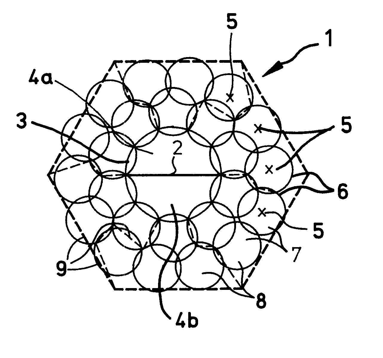
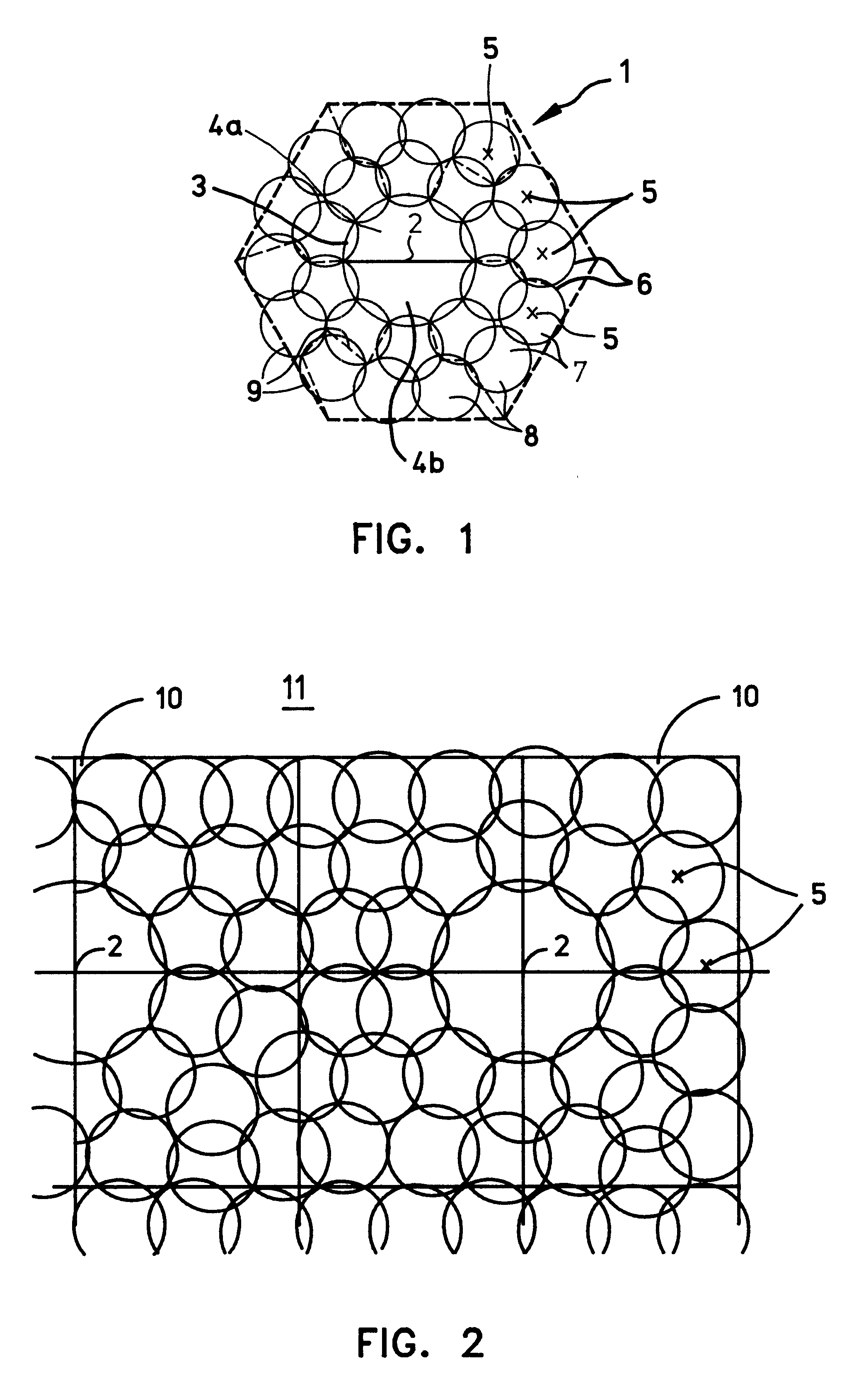
FIG. 1 shows an elementary cell 1, a large number of which can be joined together in lines to form an area-covering radio network having an approximately honeycomb structure. In the centre of the cell 1 is a base transceiver station 2, which is coupled via cable or radio link to a base station controller (not shown). By means of two directional aerials having a range 3, the central transceiver station 2 serves the inner cells 4a and 4b. Within the cells 4a or 4b, a mobile station (not shown) communicates direct with the central transceiver station 2.

In the case shown in FIG. 1, the central transceiver station 2 is surrounded by decentral transceiver stations 5, each having an identical range 6. In the arrangement shown in FIG. 1, the ranges 6 of the decentral radio stations 5 are approximately half as large as the range of the central radio station 2, which is achieved by suitable setting of the levels of transmission power. Thus the ideally circular cells 7 of the decentral transce...


PUM


Abstract

An arrangement of an area covering, cellular radio communication network having cell regions which can be contiguously replicated without interference. A central transceiver station is coupled to a base station controller and has a plurality of decentral transceiver stations surrounding and coupled to the central transceiver station. Groups of adjacent decentral transceiver stations are grouped in respective cell areas. All of the decentral transceiver stations in each cell area are allocated the same transmission frequencies, but the frequencies of each cell area are different from the other cell areas in the cell region.

Description

The invention relates to a plurality of arrangements of base transceiver stations of an area-covering radio network and to a method of operating such an arrangement.The invention further comprises base transceiver stations adapted to the new arrangements and a method of subsequently compressing an existing continuous radio network.DESCRIPTION OF RELATED ARTIn order to operate radio telephones, in addition to the respective mobile stations, an area-covering network of fixed transmission stations is necessary in order to ensure interference-free radio operation at any location within the area of coverage.In order to permit a large number of mutually independent radio participants to use their telephones simultaneously, the region of coverage is divided into a plurality of individual cells, each allocated with its own base transceiver station. By giving adjacent zones different frequencies, it is possible to identify a particular radio telephone with a respective base transceiver stati...

Claims


Application Information

Patent Timeline
Patent Type & Authority Patents(United States)
IPC IPC(8): H04B7/26H04Q7/36H04Q7/30H04W16/02H04W16/12H04W16/24H04W16/26
CPCH04B7/2609H04W16/02H04W16/12H04W16/26H04W16/24
Inventor SCHEINERT, STEFAN
Owner LITTLEFEET
Why Eureka
Try Eureka