Electrically powered steering device

a steering device and electric technology, applied in the direction of gearing, servomotors, transportation and packaging, etc., can solve the problems of impracticality, inability, interference with the inner diameter of the rotor,

Inactive Publication Date: 2002-10-15
NTN CORP
View PDF13 Cites 56 Cited by
  • Summary
  • Abstract
  • Description
  • Claims
  • Application Information

AI Technical Summary

Problems solved by technology

Although in such case the employment of multi-thread grooves capable of increasing the load capacity is advantageous, the employment of the multi-thread grooves requires the bridge member 5d for returning the balls to be disposed so as to straddle the adjacent ball guide passage and, therefore, the employment of the multi-thread grooves is impractical and impossible.
Also, where a rack or the like is provided on the outer periphery of the nut, areas to be machines are limited and, therefore, the phase of the ball screw aligned with a neutral position of the ste...

Method used


Image

  • Electrically powered steering device
  • Electrically powered steering device
  • Electrically powered steering device

Examples


third embodiment

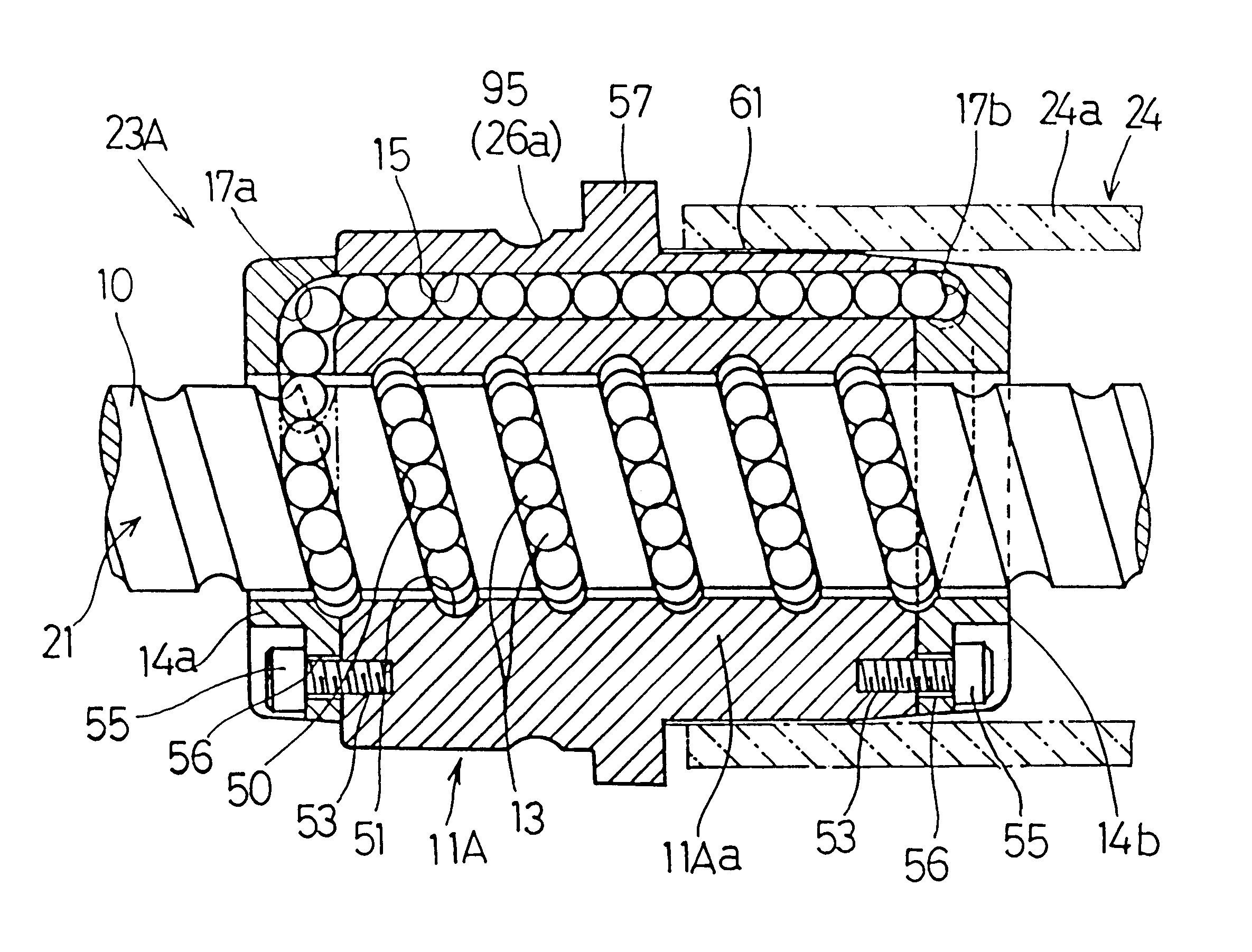
This electrically powered steering device according to the third preferred embodiment is substantially similar to that according to the first preferred embodiment except that the ball screw mechanism 23B different from the ball screw mechanism 23 is employed. Specifically, in the ball screw mechanism 23B employed in the present invention, the end cap 14a is dispensed with.

The ball screw mechanism 23B will now be described with particular reference to FIGS. 11 to 14. The illustrated ball screw mechanism 23B includes the ball screw shaft 10, the rotary nut 10B and the group of the balls 13 interposed between the ball screw shaft 10 and the rotary nut 11B.

The ball screw mechanism 23B is of a type wherein one of the end caps is formed integrally with the nut body and is hence an integral part of the rotary nut. Specifically, the rotary nut 11B includes the nut body 11Ba and the end cap 14b firmly connected to one end of the nut body 11Ba. The end cap 14b is in the form of a ring having ...

second embodiment

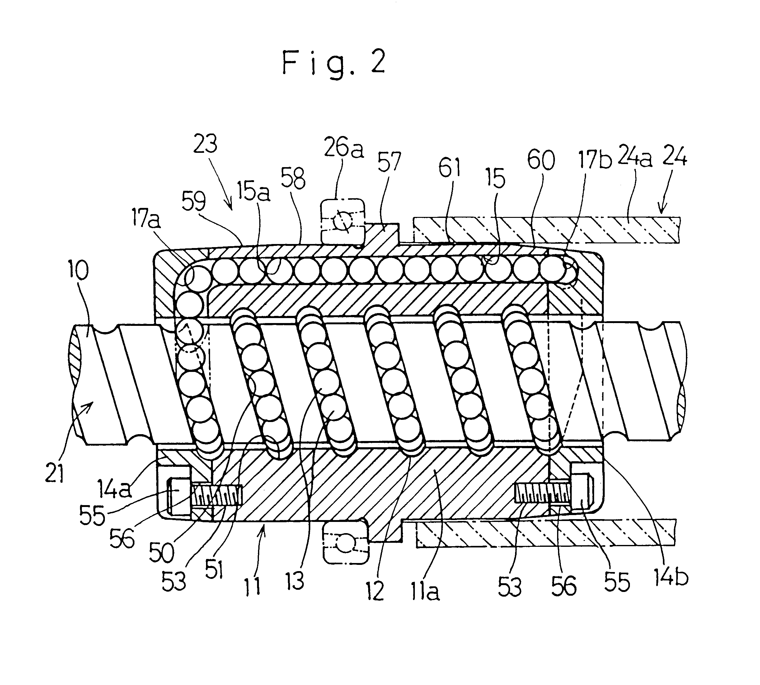
It is to be noted that as is the case with the present invention, the inner race raceway for the rolling bearing 26a can be formed integrally on the outer peripheral surface of the rotary nut 11B of the ball screw mechanism 23B.

The electrically powered steering device according to a fourth preferred embodiment of the present invention employs the ball screw mechanism that is substantially similar to that according to any one of the first to third embodiment of the present invention, except that the ball screw mechanism employed in the practice of the fourth embodiment of the present invention includes a plurality of ball circulating passages and the tapered surface on the outer peripheral surface of the end of the rotary nut is dispensed with.

fourth embodiment

Referring to FIG. 15, there is shown a schematic sectional view of the ball screw mechanism employed in the practice of the fourth preferred embodiment of the present invention. As shown therein, the ball screw mechanism 23C includes the ball screw shaft 10 having the spiral outer groove 50 formed on the outer peripheral surface thereof in the form of a multi-threaded groove (for example, double-threaded groove as shown in FIG. 15), the rotary nut 11C having the spiral inner groove 51 formed on the inner peripheral surface thereof in the form of a correspondingly multi-threaded groove, and the group of the torque transmitting balls 13 disposed in series with each other in the ball rolling guideway 12 defined between the spiral outer and inner grooves 50 and 51. As shown in FIG. 15, the balls 13 are turned in a grooved reversing guideway 17a, defined in the end cap 14a at, for example, a left end of the nut body 11Ca as viewed in FIG. 15, so as to travel into a circulating tunnel 15C...


PUM


Abstract

An electrically powered steering device comprises a ball screw mechanism for transmitting a steering force from a steering wheel to steerable vehicle wheels. The ball screw mechanism includes a rotary nut 11 having a nut body 11a in which a circulating passage 15 is formed so as to extend axially thereof, and end caps 14a and 14b secured respectively to opposite ends of the nut body 11a. Each of the end caps 14a and 14b has defined therein respective guideways 17a and 17b for balls 13 that communicate opposite ends of the circulating tunnel 14 with a ball rolling passage 12. The end caps 14a and 14b and the nut body 11a are made of a sintered alloy. The nut body 11a has an outer periphery of one end thereof that is axially progressively reduced in diameter to define a tapered surface.

Description

1. Field of the InventionThe present invention generally relates to an electrically powered steering device for an automotive vehicle and, more particularly, to the electrically powered steering device employing a ball screw mechanism for transmitting a drive output from an electric motor to a steering shaft to selectively advance and retract the latter.2. Description of the Prior ArtThe electrically powered steering device is an instrument to assist the steering force of a steering wheel by means of an electrically driven motor and is currently available in various types. One of the types employed is of a design wherein a retractable steering shaft coupled with a steering mechanism for vehicle wheels is imparted an axially shifting force that is transmitted thereto from the steering wheel through a motion translating mechanism such as a rack-and-pinion mechanism for translating a rotary motion of the steering wheel into the axially shifting motion and, also, an axially shifting for...

Claims


Application Information

Patent Timeline
IPC IPC(8): B62D5/04F16H25/22
CPCB62D5/0448F16H25/2219Y10T74/18664F16H2025/249F16H2025/2242
Inventor TODA, MASAAKITATEISHI, KOJIYOSHIDA, ISAMUYAMAUCHI, KIYOSHIGEYOSHIOKA, MORIHISA
Owner NTN CORP
Why Eureka
Try Eureka