High speed laser triangulation measurements of shape and thickness

a laser and shape technology, applied in the direction of geological measurements, instruments, surveying and navigation, etc., can solve the problems of ambiguity, limiting accurate mensuration at high speed, cost of multiple camera frames, lost time, etc., to achieve the highest possible operational speed, avoid ambiguity, and achieve acceptable accuracy.

Inactive Publication Date: 2002-10-15
LMI TECH
View PDF9 Cites 44 Cited by
  • Summary
  • Abstract
  • Description
  • Claims
  • Application Information

AI Technical Summary

Benefits of technology

The technical effect of this patent is to create a device that uses cameras and lasers to accurately measure objects quickly and easily. This helps overcome any issues caused by uneven surfaces and ensures accurate results without being too expensive.

Problems solved by technology

The technical problem addressed in this patent text needs to be identified by a senior R&D personnel.

Method used


Image

  • High speed laser triangulation measurements of shape and thickness
  • High speed laser triangulation measurements of shape and thickness
  • High speed laser triangulation measurements of shape and thickness

Examples


Embodiment Construction
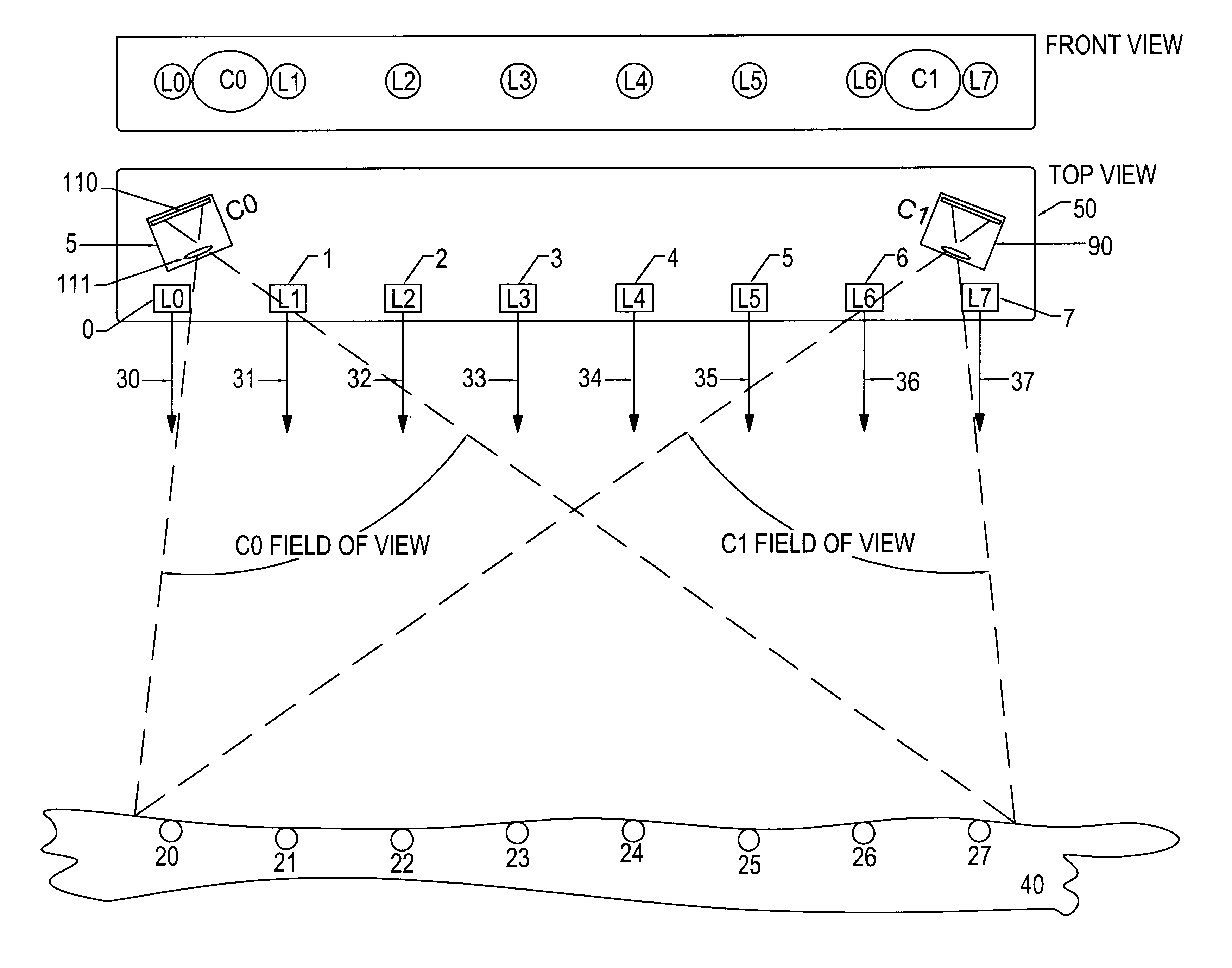
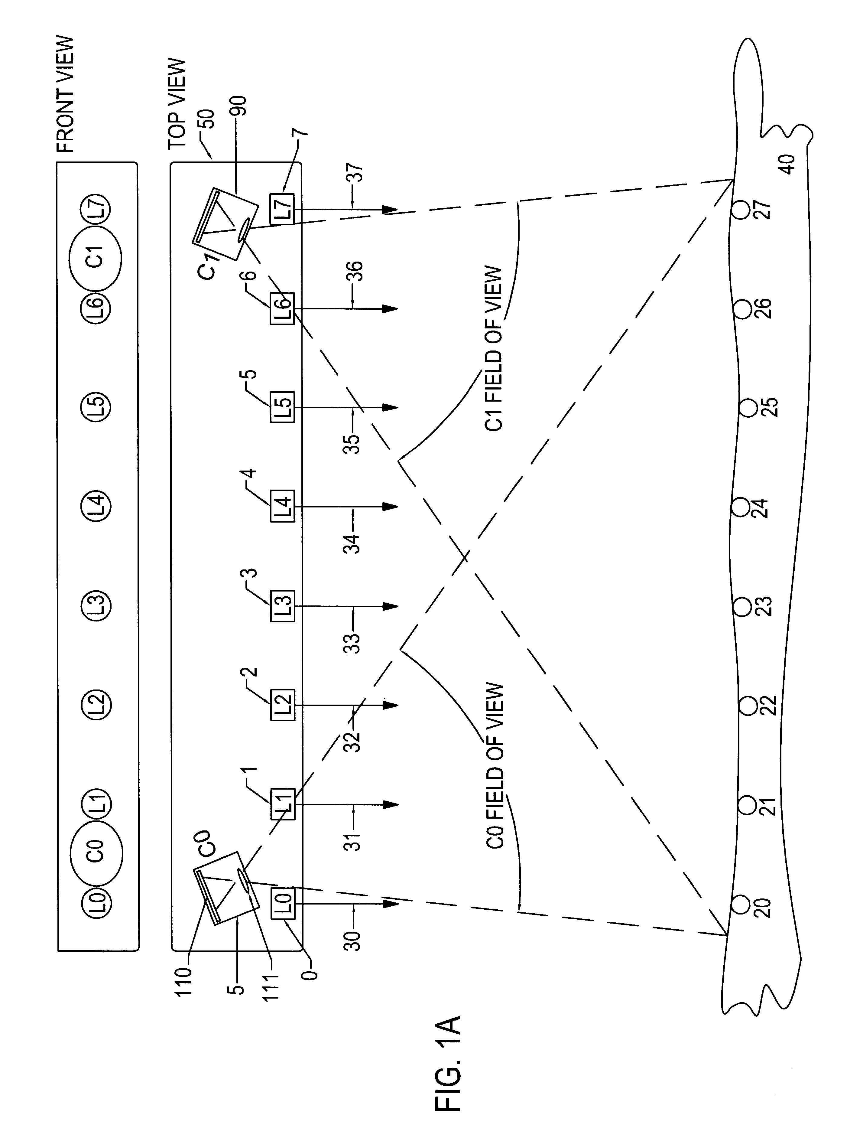
FIG. 1

FIG. 1 here presented is similar to that of the Leong et al reference above, though it employs discrete lasers as illumination sources. This is much more useful as it allows higher power per projected zone on the object surface, and easier modulation of the zones on and off (or to other power levels). It is of use in profiling the shape or thickness of objects in multiple sections, such as desirable for determining parameters of ostensibly flat boards in sawing operations in lumber mills.

When a camera 5 (comprising a photodetector array such as 110 and lens 111) is oriented so as to be in the same plane as the projected zones 20-27 on the object 40 from laser beams 30-37 (generated by lasers 0-7), the distance of the object 40 from each discrete laser illumination point on the scan head 50 can be determined via triangulation, as discussed in the prior art references above. Measurement can be achieved for example using either in a triangulation model calculation, or via empiric...


PUM


Abstract

This application is concerned with laser triangulation sensors for object dimension and position determination, and in particular, more effective measurement of object shapes and/or thickness using laser triangulation sensors having multiple projected laser beams and at least two linear or matrix array cameras to view the images of light reflected from the object due to the beams impinging on the object surface. Besides disclosure of the basic operation of "multi-point" sensors of this type, novel methods and apparatus are also disclosed to assure function of the device even with objects, such as lumber, having pronounced protrusions and depressions in their surface.

Description


Claims


Application Information

Patent Timeline
Owner LMI TECH
Why Eureka
Try Eureka