Method for deploying a parachute on a drone

a parachute and drone technology, applied in the direction of launching weapons, floating objects, emergency apparatus, etc., can solve the problems of drone loss, drone cannot make an emergency landing, crashes or self-destruct,

Inactive Publication Date: 2002-10-29
AIRBUS HELICOPTERS DEUT GMBH
View PDF5 Cites 43 Cited by
  • Summary
  • Abstract
  • Description
  • Claims
  • Application Information

AI Technical Summary

Benefits of technology

The above objects have been achieved according to the invention in a drone air vehicle and a method of deploying a parachute from the drone. According to the invention, signals and / or data are supplied from at least flight-relevant subsystems such as the power supply system, the propulsion system and the actuating drive system to an error detection device via signal connections and / or data connections. The error detection device detects errors or error combinations according to a program and then, in response to detecting such an error or error combination, supplies a signal to the parachute system so that the parachute system forms a control signal which causes ejection of the parachute by the ejection mechanism. Thus, if a critical error condition (which would likely lead to lack of control and / or crashing of the drone) is detected, the drone will automatically and self-sufficiently be deactivated and will be carried safely down to the ground or water on the deployed parachute. With the inventive arrangement and method, it is not necessary to provide redundancy of the various systems, i.e. single systems can be provided without backup, because the drone can be safely recovered even if one or more of its singly provided subsystems suffers an error or failure.
The invention provides the advantage, despite the use of single systems, i.e. without redundantly duplicating flight-relevant systems, of nevertheless providing a reduced risk of losing the drone. Thus not only can development and production costs be reduced, but also the costs of operating the drone can be reduced as it can carry an increased payload and / or has a reduced fuel requirement.

Problems solved by technology

These are error-critical subsystems, whereby an individual failure of a subassembly from one of these systems frequently leads to the loss of the drone.
In the case of failure, such a drone cannot make an emergency landing.
It crashes or self-destructs.
Such a case of failure can endanger the immediate surroundings in the area of the crash or destruction of the drone.
However, this solution leads to a drastic increase of the flying weight of the drone, so that a more powerful propulsion system is required.
The conventional approach is thus very intensive in materials and costs, both in the original manufacturing and in the ongoing operation of the drone.

Method used


Image

  • Method for deploying a parachute on a drone
  • Method for deploying a parachute on a drone

Examples


Embodiment Construction

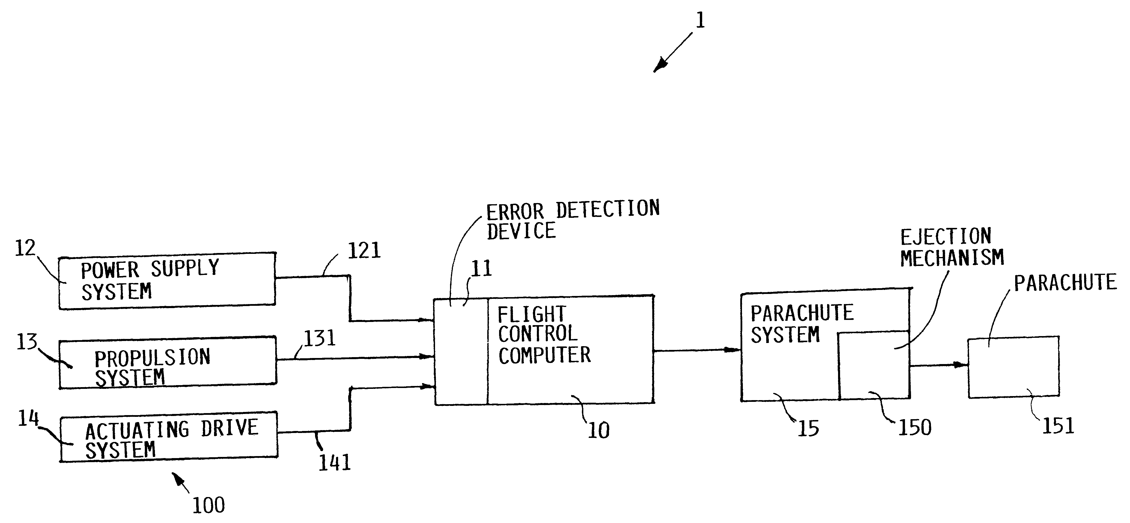
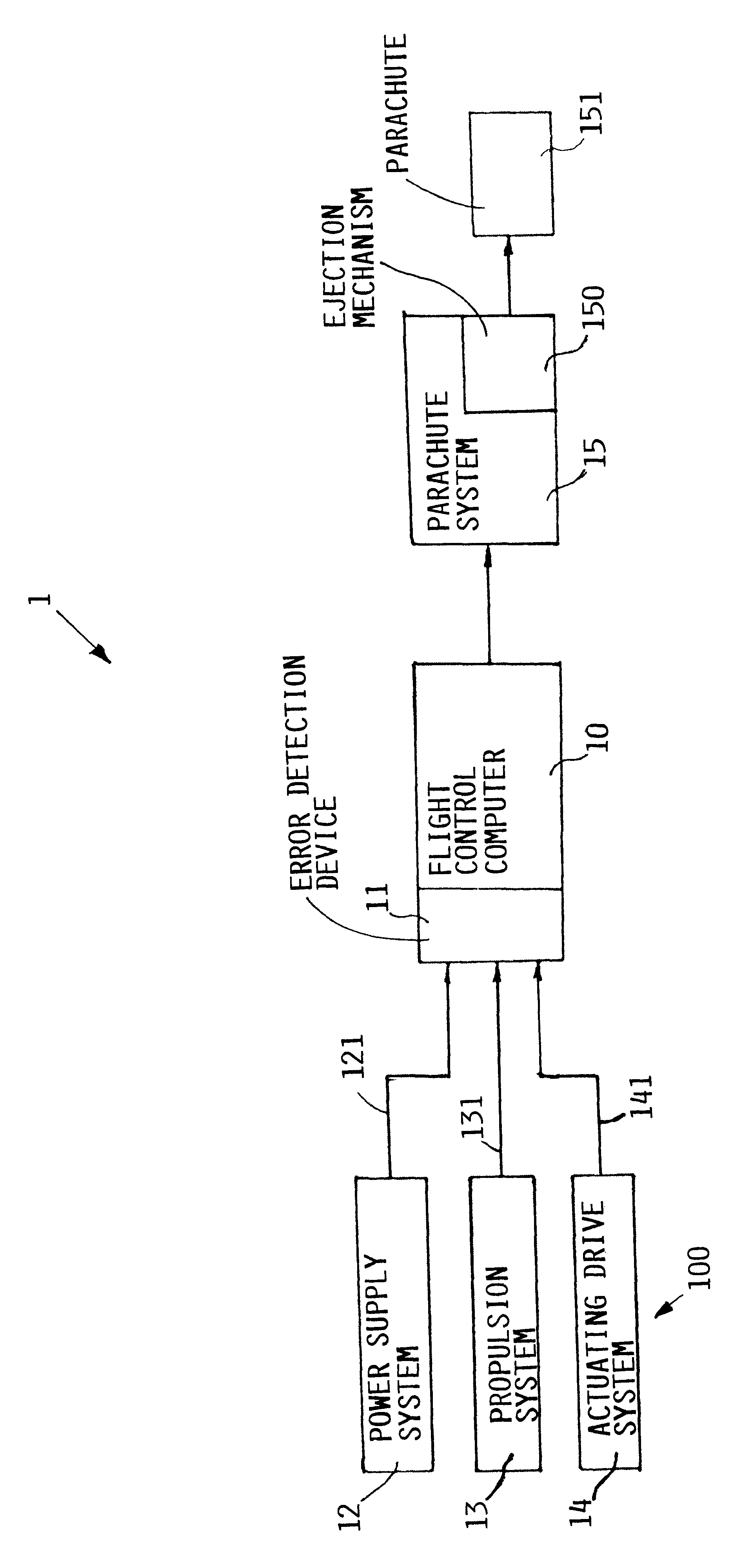
The control arrangement 1 according to the single FIGURE includes a flight control computer 10 of a drone air vehicle. The flight control computer 10 is connected to subordinate subsystems 100 of the drone, which are controlled or regulated by the flight control computer 10. The flight control computer 10 receives information from failure-relevant subsystems 100, such as for example a power supply system 12 via the signal and data connection 121, a propulsion system 13 via the signal and data connection 131, and an actuating drive system 14 via the signal and data connection 141.

The power supply system 12, the propulsion system 13, and the actuating drive system 14 may each individually be embodied according to any known conventional teachings for such systems in air vehicles and particularly in drones. For example, the propulsion system 13 may comprise any known jet engine, turbine engine, or a combustion engine coupled to a drive propeller, or the like. The actuating drive system ...


PUM


Abstract

A flying drone includes a flight control computer, a parachute system with a parachute, a power supply system, a propulsion system, and an actuating drive system, without any of these systems being redundantly duplicated. To prevent uncontrolled crashing of the drone due to a critical error of any subsystem, signals or data are supplied from the power supply system, the propulsion system, and the actuating drive system, to an error detection or recognition device, which detects defined errors or error combinations in the provided signals or data and then supplies a deployment signal to the parachute system, which responsively generates a control signal that triggers an ejection mechanism to eject the parachute.

Description

PRIORITY CLAIMThis application is based on and claims the priority under 35 U.S.C. .sctn.119 of German Patent Application 100 26 469.7, filed on May 27, 2000, the entire disclosure of which is incorporated herein by reference.The invention relates to a method of deploying a parachute on a drone air vehicle so as to avoid an uncontrolled crash of the drone.BACKGROUND INFORMATIONA drone is an unmanned airborne vehicle for civil or military applications, for example for area reconnaissance. The drone is generally programmed or controlled to land according to plan in a desired location, once its mission is fulfilled. To this effect a control device of the drone activates a parachute system according to a program, so that the parachute system ejects and activates a parachute connected to the drone. The drone lands in the target area by means of the parachute. It is known that the drone can trigger the parachute system by means of a flight control computer and its program, integrated in t...

Claims


Application Information

Patent Timeline
Patent Type & Authority Patents(United States)
IPC IPC(8): B64D17/62B64D17/80B64D17/00B64C39/00B64C39/02
CPCB64D17/80B64C2201/185B64U70/83
Inventor GRIESER, WOLFRAM
Owner AIRBUS HELICOPTERS DEUT GMBH
Why Eureka
Try Eureka