Method of correcting thermal displacement of machine tool

a technology of machine tools and thermal displacement, which is applied in the direction of motor/generator/converter stoppers, electric programme control, and electrical programme control, etc., can solve the problems of increasing machining time, affecting the structure or affecting the position of the sensor, etc., and achieves low cost and easy correction of thermal displacement.

Inactive Publication Date: 2002-10-29
FANUC LTD
View PDF6 Cites 44 Cited by
  • Summary
  • Abstract
  • Description
  • Claims
  • Application Information

AI Technical Summary

Benefits of technology

An object of the present invention is to provide a method of correcting thermal displacement in which thermal displacement can be corrected easily and at a low cost without the need for a sensor.
According to the above-described method of correcting thermal displacement of the second embodiment, for each of divisional sections obtained by dividing the entire stroke of the feed shaft, the effect of the generated heat at the section to which the feed screw has actually moved, and the effect of the generated heat transmitted by thermal conduction from the adjacent section, are estimated for each section. The thermal displacement for each section is added from the reference point to the correction position. Thus, accurate correction which does not depend on the position can be carried out. Further, by considering the effects of the spindle and the feed shaft, accurate correction can be carried out.
According to the method of correcting thermal displacement of the present invention, thermal displacement can be corrected simply and at a low cost, without the need for a sensor.

Problems solved by technology

This displacement of the tool position due to heat is problematic in cases where highly precise machining is to be carried out.
However, in the method in which an initial tension is imparted to the ball screw at the feed screw so as not to be influenced by an expansion due to heat and in the method in which a sensor is provided and the thermal displacement is corrected, there are problems concerning limits to the structure or position where a sensor is mounted, or problems in that means is needed to protect the sensor from coolant and chips for maintaining reliability of the sensor.
Further, in a case where a sensor is provided, problems arise in that time is required for measurement, and as a result, the machining time increases, and displacement cannot be corrected at the time of start-up of the machining operation.

Method used


Image

  • Method of correcting thermal displacement of machine tool
  • Method of correcting thermal displacement of machine tool
  • Method of correcting thermal displacement of machine tool

Examples


embodiments

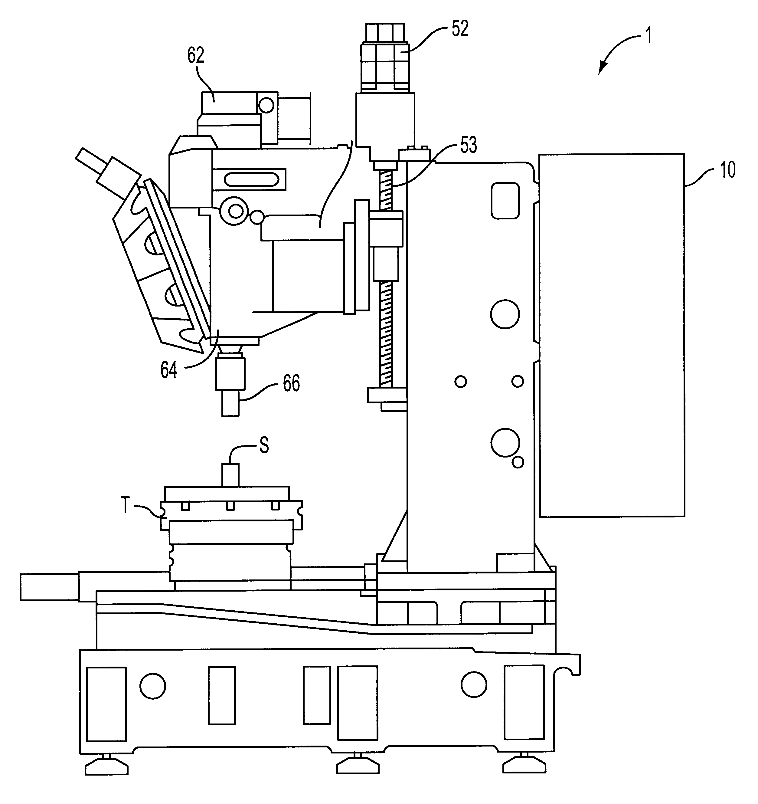
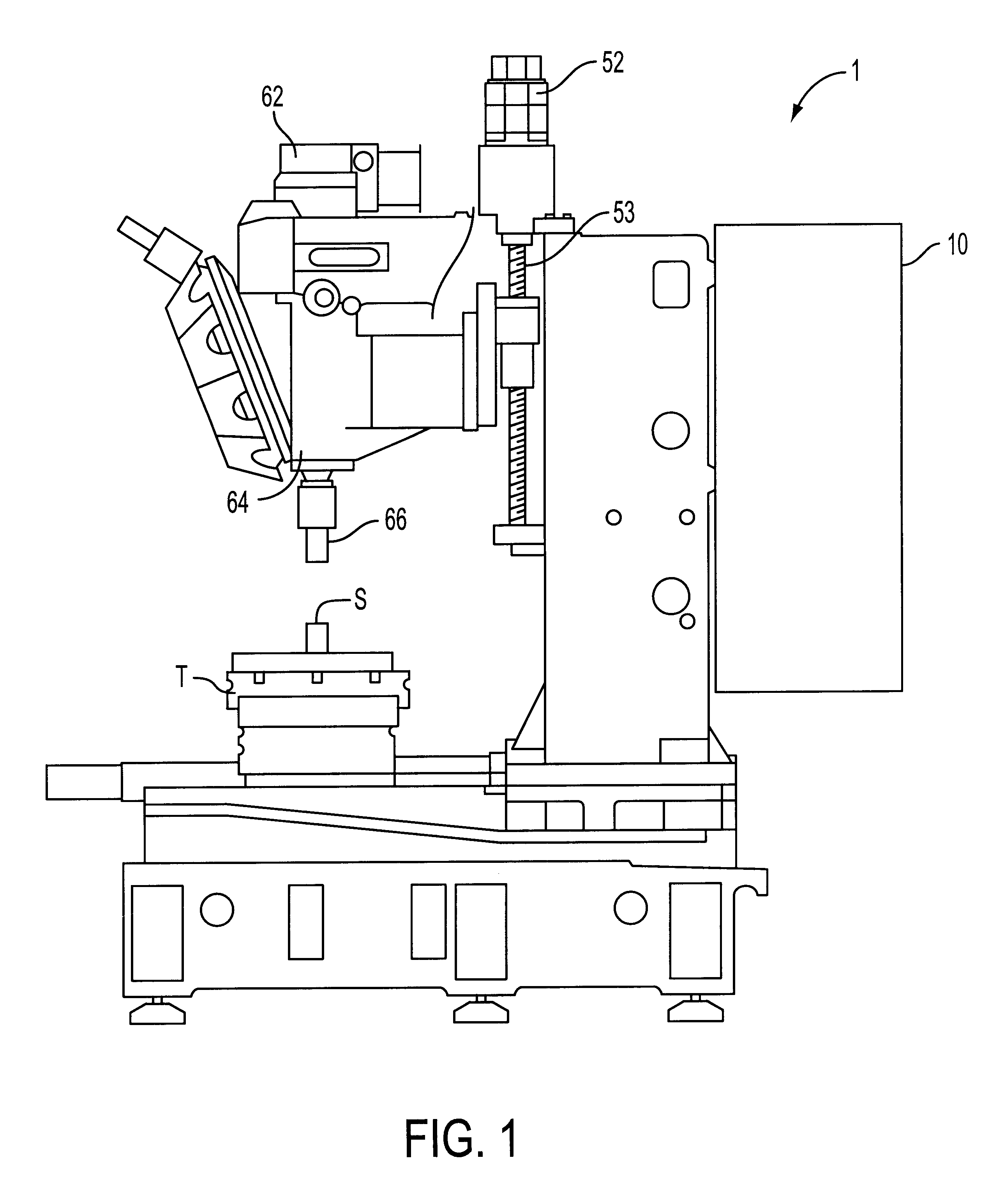
FIG. 1 is a schematic view of a vertical type drill press 1 of a machine tool to which the present invention is applied.

In FIG. 1, reference numeral 62 is a spindle motor, 52 is a servo motor for a Z shaft which is a vertical feed shaft, 10 is a numerical control device (CNC) which serves as a control device for controlling the drill press, 64 is a spindle, and 66 is a tool mounted to a spindle 64B. The table T is moved in directions of an X shaft and a Y shaft, which are orthogonal to the Z shaft and perpendicular to one another, by unillustrated servo motors for the X shaft and Y shaft. The structure of the drill press 1 is no different than conventional structures, and thus, further explanation thereof will be omitted.

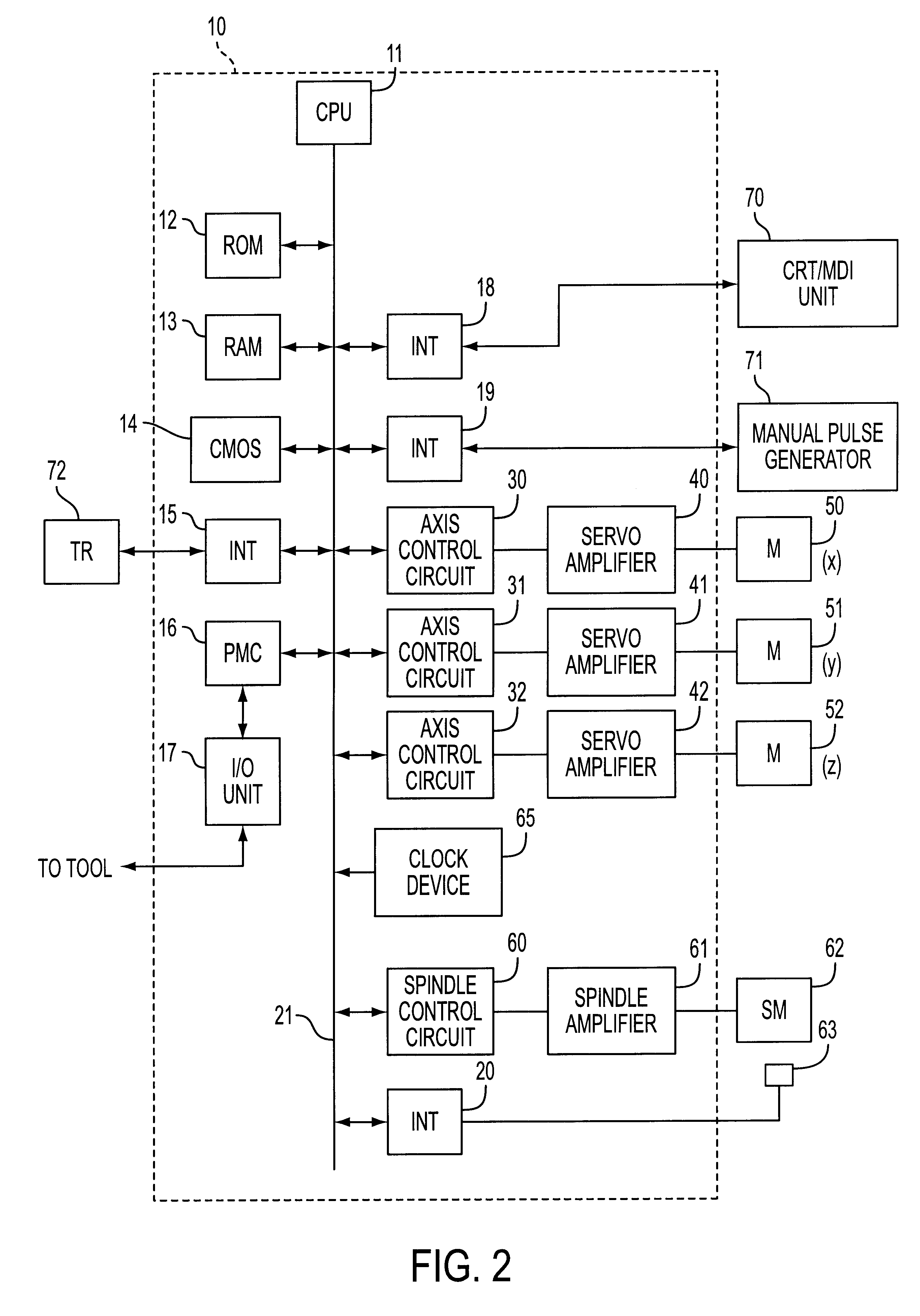
FIG. 2 is a functional block-diagram showing main portions of the numerical control device 10 of the above-described drill press.

A processor 11 of the numerical control device 10 is a processor which overall controls the numerical control device 10. The processor 11...

first embodiment

First, the present invention will be described.

In the present embodiment, thermal displacement, which arises from heat generation due to rotation of the spindle and from heat generation due to conduction of the heat generated by driving the spindle motor, is determined. In this case, as the thermal displacement of the spindle is expressed as a positional displacement of the Z axis, the thermal displacement of the spindle is determined by measuring the positional displacement of the Z axis.

In the measurement of the thermal displacement, the spindle motor is rotated at a predetermined rotational speed, and each time a predetermined interval of time passes, the height of the displacement measuring apparatus is adjusted, and the distal end operation surface of the tool is made to contact from the direction of Z axis, and the thermal displacement of the spindle is thereby measured. As for the measurement data, a plurality of types of data can be determined by changing the rotational spee...

second embodiment

Next, the present invention will be described.

In the present embodiment, the entire stroke of the feed shaft is divided into a finite number of sections, and thermal displacement correction for the feed shafts is carried out by using the thermal displacement for each of the divisional sections.

FIG. 5 is a schematic diagram for explaining the divisional sections of the feed shaft. In FIG. 5, the entire stroke of the feed shaft is divided into X+1 sections, from a section 0 (a section adjacent to a reference position) to a section X (the section the furthest from the reference position).

The thermal displacement .delta..sub.nI of a section I at a time n is expressed by the following equation.

.delta..sub.nI =.delta..sub.(n-1)I +A3.sub.nI -B3.sub.nI +D.sub.nI (8)

wherein

D.sub.nI =k5.multidot.{.delta..sub.(n-1)I+1 +.delta..sub.(n-1)I-1 -2.multidot..delta..sub.(n-1)I } (9)

Here, with n as the sampling time,

.delta..sub.nI : thermal displacement of section I

A3.sub.nI : extension of section I p...


PUM

PropertyMeasurementUnit
thermal displacementaaaaaaaaaa
speedaaaaaaaaaa
displacementaaaaaaaaaa

Abstract

In a machine tool controlled by using a numerical control device, a correction amount is determined for thermal displacement due to heat generation and heat conduction in a spindle motor and a feed shaft motor, in addition to thermal displacement due to heat generated by rotation of a spindle and a feed shaft. A tool position is corrected based on the correction amount. An entire stroke of the feed shaft is divided into a finite number of sections, and for each section, a correction amount for thermal displacement due to axial movement of the feed shaft is determined. The tool position is corrected based on the determined correction amount.

Description

1. Field of the InventionThe present invention relates to a method of correcting thermal displacement in a machine tool.2. Description of the Related ArtIn a machine tool, due to heat generated from a motor which drives a feed screw and a spindle, frictional heat caused by rotation of a bearing, and frictional heat at the joined portion of a ball screw and a ball nut, the feed screw and the spindle expand and the tool position is displaced. Namely, the relative positional relationship between the workpiece which is to be positioned and the tool becomes offset. This displacement of the tool position due to heat is problematic in cases where highly precise machining is to be carried out.As means for eliminating displacement of a tool position due to heat, conventionally, methods have been used in which a cooling apparatus is provided, or an initial tension is imparted to the ball nut at the feed screw so as not to be influenced by an expansion due to heat, or in which a displacement s...

Claims


Application Information

Patent Timeline
Patent Type & Authority Patents(United States)
IPC IPC(8): G05B19/404B23Q5/22B23Q17/09B23Q15/18
CPCG05B19/404G05B2219/49207Y10T409/303976Y10T409/303752G05B2219/49219B23Q3/15534
Inventor KOJIMA, KUNIOMAEKAWA, SUSUMU
Owner FANUC LTD
Why Eureka
Try Eureka