
Liquid discharge head, liquid discharge apparatus and method for manufacturing liquid discharge head

a liquid discharge head and liquid discharge technology, applied in printing, inking apparatus, other printing apparatus, etc., can solve the problems of difficult to detect more accurate ink condition, flow path, and flow rate cannot be detected with high accuracy

Inactive Publication Date: 2002-11-05
CANON KK
View PDF9 Cites 56 Cited by
  • Summary
  • Abstract
  • Description
  • Claims
  • Application Information

AI Technical Summary

Problems solved by technology

However, recently, as high density recording has been progressed, an amount of ink discharged by one discharging has been made smaller more and more, with the result that, rather than the temperature of the substrate, condition and kind of the ink such as temperature and density of the ink itself have affected an influence upon the recording.
In such a circumstance, in the arrangement of the temperature sensors in the conventional liquid discharge head, it was difficult to detect more correct ink condition.
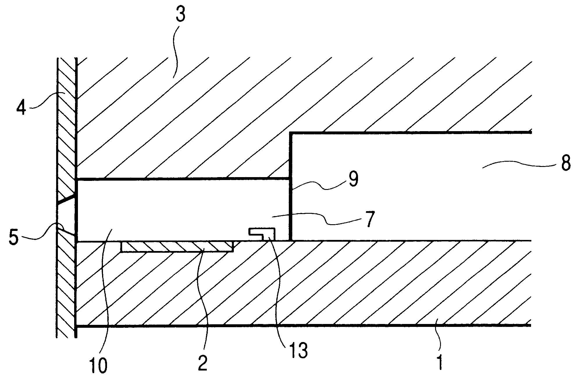
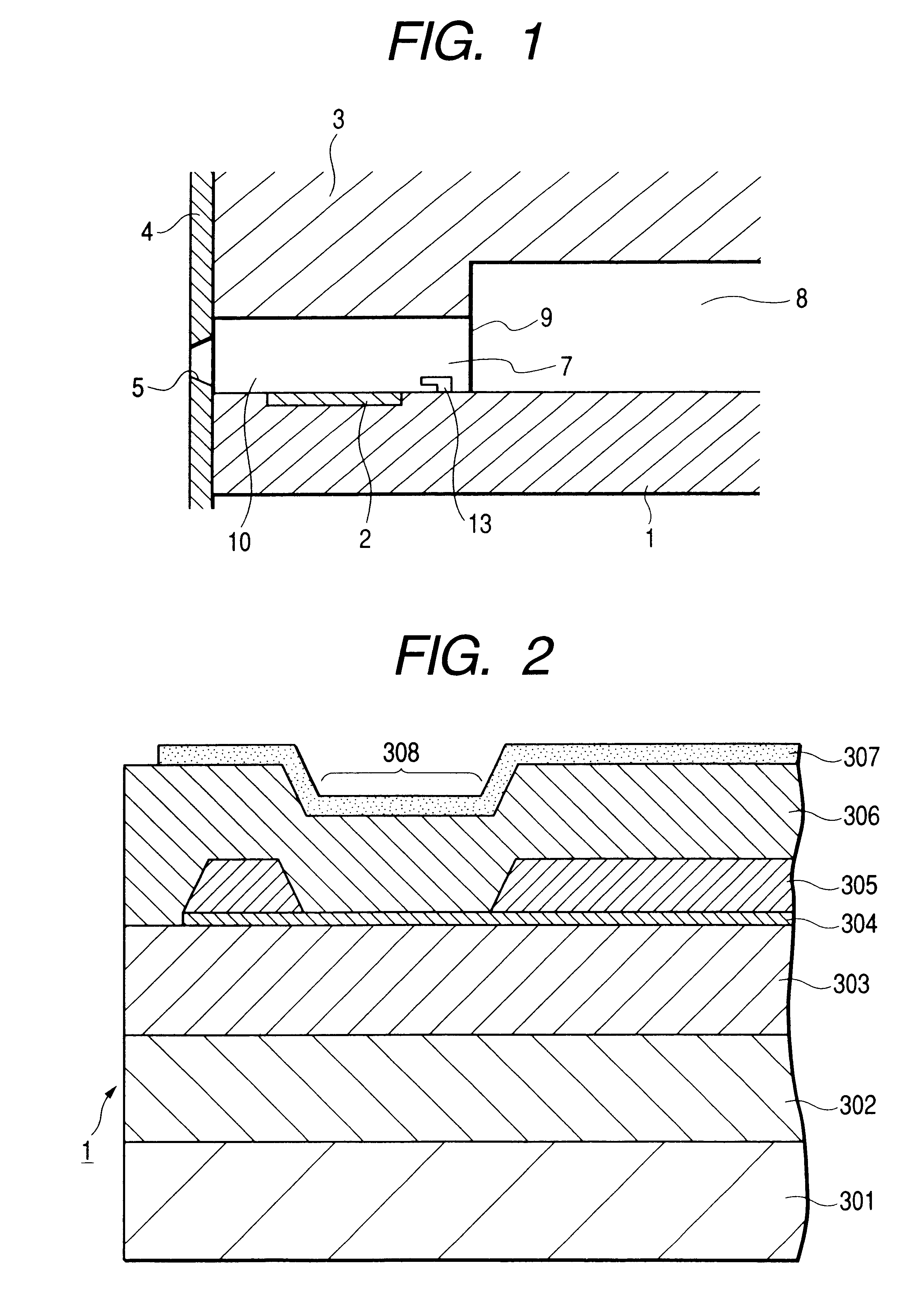
Even when a flow rate sensor is constituted in this way, in the arrangement in which the temperature sensor and the heater are arranged on the surface of the substrate, even if the liquid is locally heater, since the heat is escaped to the substrate and the flow of the liquid becomes small in the vicinity of the surface of the substrate due to the viscosity of the liquid, the flow rate cannot be detected with high accuracy in the minute flow path.
Accordingly, if such circuits are formed on the top plate 3, the connection points between the element substrate 1 and the top plate 3 are increased, with the result that the danger of causing poor connection is increased.

Method used


Image

  • Liquid discharge head, liquid discharge apparatus and method for manufacturing liquid discharge head
  • Liquid discharge head, liquid discharge apparatus and method for manufacturing liquid discharge head
  • Liquid discharge head, liquid discharge apparatus and method for manufacturing liquid discharge head

Examples


second embodiment

(Second Embodiment)

In a second embodiment of the present invention, a pressure sensor is provided on a movable member.

By arranging the movable member having the pressure sensor element in the liquid flow path, the pressure caused by the bubble generated above the heat generating element can be measured electrically by the pressure sensor element responsive to displacement of the movable member. Particularly, the bubble pressure can be guessed from an amount of displacement of the movable member in the liquid, and, by adjusting the driving condition of the energy generating element on the basis of such displacement amount, the discharge property can be stabilized.

Now, the second embodiment of the present invention will be explained with reference to the accompanying drawings.

FIG. 18 is a sectional view of a liquid discharge head according to the second embodiment, taken along a direction of a liquid flow path thereof.

As shown in FIG. 18, the liquid discharge head comprises an element...

third embodiment

(Third Embodiment)

A third embodiment of the present invention relates to a head in which movable members are provided in nozzles and dynamic viscosity of the liquid in the liquid flow paths is guessed by detecting strain during the displacement of the movable members, thereby adjusting the driving conditions of the heat generating elements. According to this arrangement, a recording head and a recording apparatus, in which dynamic viscosity of the liquid in each nozzle is monitored and liquid droplet discharge associated with each heat generating element can be stabilized can be provided.

More specifically, in a liquid discharge head wherein, in first and second substrates joined together to define a plurality of liquid flow paths communicated with a plurality of corresponding discharge ports for discharging liquid, there are provided a plurality of energy generating elements disposed in the respective liquid flow paths to generate discharge energy for discharging the liquids from th...

fourth embodiment

(Fourth Embodiment)

In a fourth embodiment of the present invention, viscosity sensors are provided in the liquid flow paths.

In a liquid discharge head filled with liquid including moisture, if the discharge is not carried out for a long term, moisture in the liquid stayed in the discharge ports and therearound is vaporized to increase viscosity of the liquid, with the result that there may exist dispersion in discharge amounts of liquid discharged from the discharge ports or the liquid may be adhered to the discharge ports to cause defective discharge. Further, due to change in dye (pigment) density, quality of an image formed on the recording medium may be worsened.

In the past, the control of the discharge amount was effected on the basis of the temperature of the element substrate including the electrical / thermal converters and / or an environmental temperature. Further, in order to prevent the defective discharge, preliminary discharge as discharge recovery operation has been perfo...


PUM


Abstract

The present invention provides a liquid discharge head comprising a plurality of discharge ports for discharging liquid, first and second substrates for defining a plurality of liquid flow paths communicated with the discharge ports, and a plurality of energy converting elements disposed in the liquid flow paths and adapted to convert electrical energy into discharge energy for liquids in the liquid flow paths, wherein sensors for detecting behavior of the liquid are provided in the respective liquid flow paths as solid structure portions protruded from walls of the liquid flow paths.

Description

1. Field of the InventionThe present invention relates to a liquid discharge head for discharging a desired liquid by generating a bubble created by acting thermal energy to the liquid, a method for manufacturing such a liquid discharge head, and a liquid discharge apparatus.2. Related Background ArtAn ink jet recording method, i.e., a so-called bubble jet recording method in which a condition change including abrupt volume change (generation of bubbles) is generated and ink is discharge from a discharge port by an action force based on the condition change and the discharged ink is attached to a recording medium to form an image on the recording medium is well known. As disclosed in U.S. Pat. No. 4,723,129, in a recording apparatus utilizing such a bubble jet recording method generally includes discharge ports for discharging the ink, ink flow paths communicated with the discharge ports, electrical / thermal converters (as energy generating means) disposed in the ink flow paths and a...

Claims


Application Information

Patent Timeline
Patent Type & Authority Patents(United States)
IPC IPC(8): B41J2/14B41J2/05B41J2/16
CPCB41J2/04541B41J2/04543B41J2/04553B41J2/04563B41J2/04571B41J2/0458B41J2/14048B41J2/14072B41J2/14129B41J2/14153B41J2/1604B41J2/1628B41J2/1629B41J2/1631B41J2/1642B41J2002/14354B41J2202/13
Inventor IMANAKA, YOSHIYUKIYAMANAKA, AKIHIROOZAKI, TERUOKUBOTA, MASAHIKOWATANABE, SHINJITANEYA, YOICHISUGIYAMA, HIROYUKI
Owner CANON KK
Learn More