Tamper-proof display

a display and display technology, applied in the direction of machine supports, shaping building parts, domestic objects, etc., can solve the problems of unsightly cables prominently visible on the display counter, battery wearout, damage,

Inactive Publication Date: 2002-11-05
CDA INDS
View PDF4 Cites 152 Cited by
  • Summary
  • Abstract
  • Description
  • Claims
  • Application Information

AI Technical Summary

Problems solved by technology

It is usually preferable to use a remote power supply rather than the batteries supplied with the device, because the batteries may run down when the video camera is being tested by a prospective purchaser and the batteries will wear out if they are cycled repeatedly.
Further, unless the hole in the display counter is large, which is unsightly, or specially lined, the cable will chafe and suffer damage as it is drawn out of, and pushed into, the hole.
Therefore, the earlier security display system results in unsightly cables prominently visible on the display counter: at the minimum, running directly from the display item to the hole in the display counter, but more likely, strewn upon the display counter.
However much cable is on the display counter and whichever way it arrives there, its presence is unsightly and detracts from the desired presentation of the display item.
However, if they do remount the display item there is no reason for them to orient the display item to its best advantage for the purposes of the person who is displaying it.

Method used


Image

  • Tamper-proof display
  • Tamper-proof display
  • Tamper-proof display

Examples


Embodiment Construction

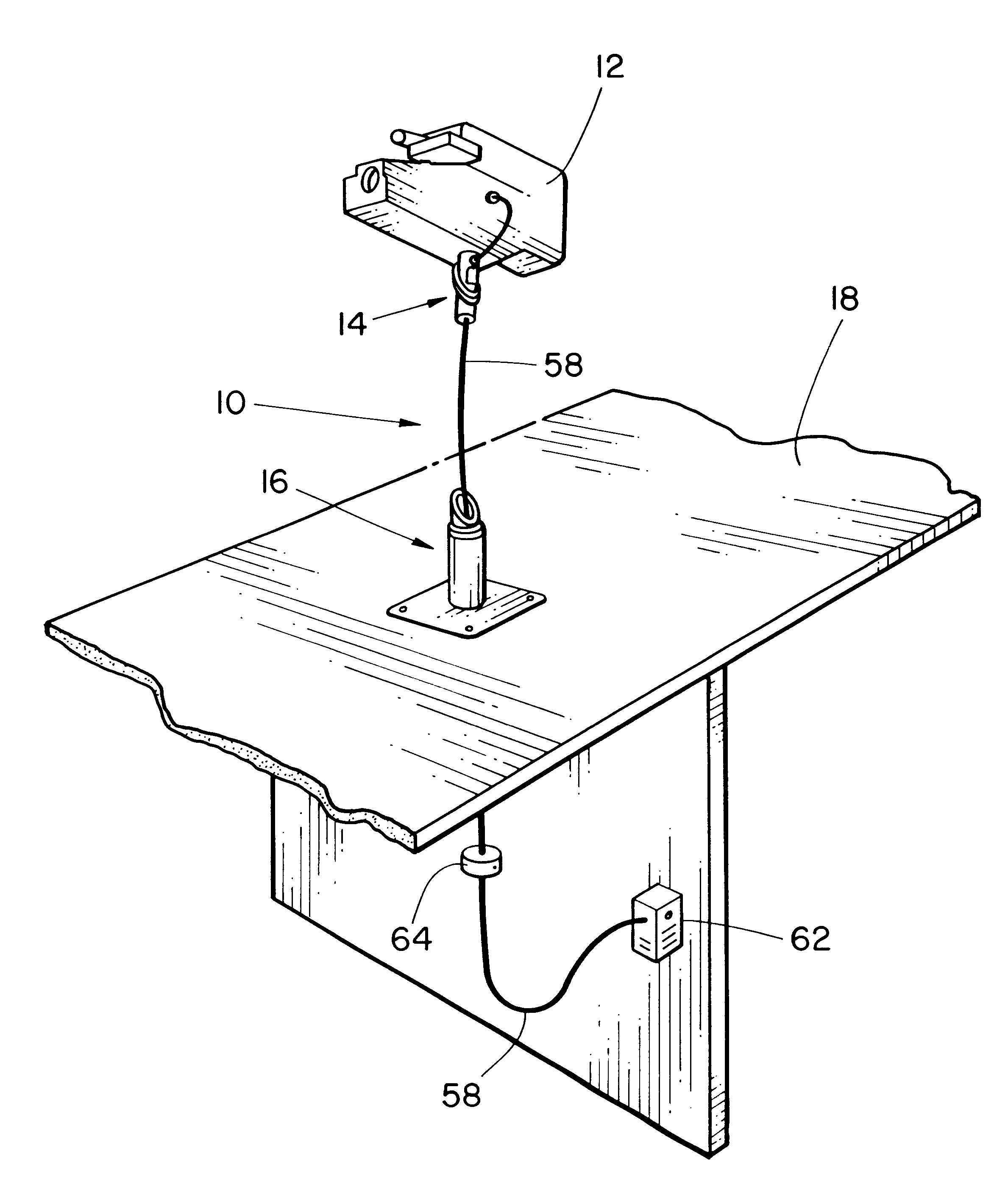
The security display system 10 illustrating the present invention is shown in FIG. 1. The display item 12 shown in FIG. 1 is a video camera. The display item 12 is attached to the mount 14. The pedestal 16 is attached to the display counter 18.

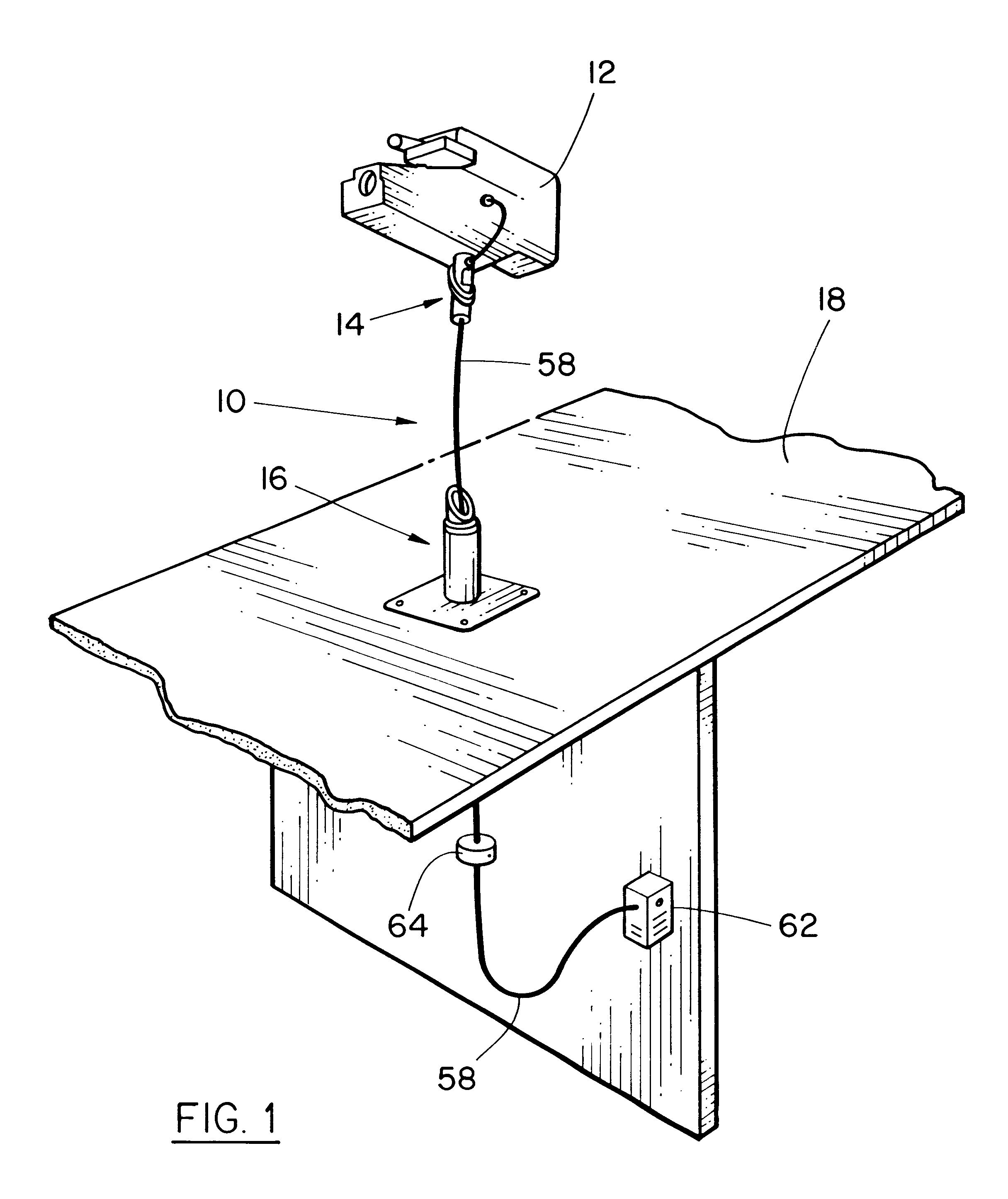
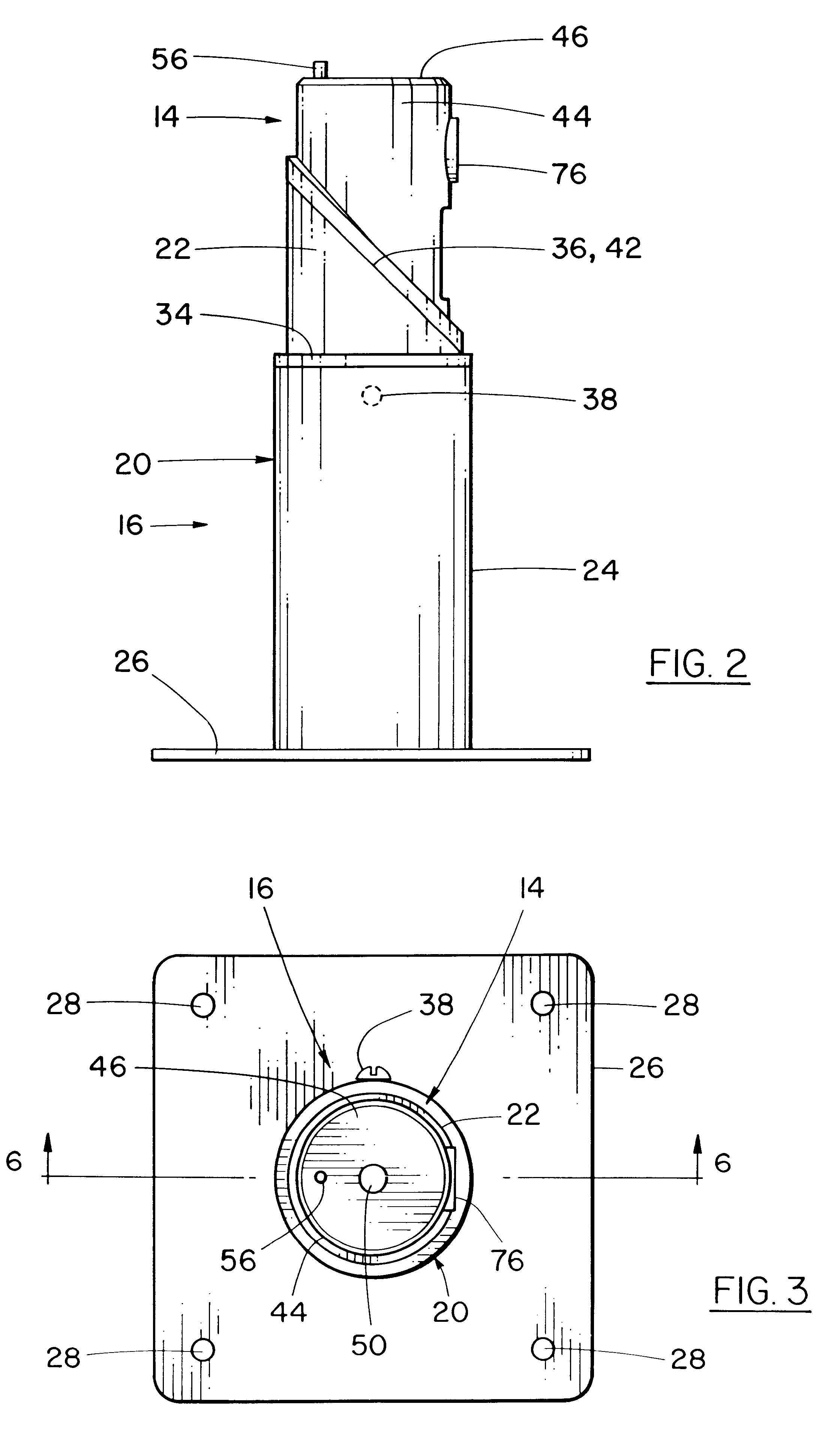
The pedestal 16 is composed of the pedestal bottom 20 and the shoulder 22. In the illustrative embodiment the pedestal bottom 20 consists of a cylinder 24 attached at one end to, and substantially normal to, a base 26. As shown in FIG. 3, the base 26 has fastener holes 28 so that it can be attached to a display counter 18 with bolts, screws or other appropriate fasteners. As shown in FIG. 6, the pedestal bottom bore 30 runs through the base 26 and runs the length of the cylinder 24.

The shoulder 22 is a cylindrical annulus with a shoulder bore 32, an insertion stop 34 and a shoulder positioning surface 36. The external diameter of the shoulder 22 is sufficiently less than the diameter of the pedestal bottom bore 30 so that the shoulder 22 may b...


PUM


Abstract

A security display system typically used to display, and permit the handling of, costly items such as cameras, video cameras and recorders, while preventing the theft of those items. The system permits persons to handle the item and prevents theft of the item through a cable which acts to tether the item, provide power to the item and trigger an alarm if it is cut or disconnected. The cable is largely hidden until the item is picked up, as the cable runs through the item support and under the counter.

Description

1. Field of the InventionThe present invention relates to a security display system typically used as a retail store display, and permits the handling of costly items such as cameras, video cameras and recorders, while preventing the theft of those items. The display can also be used at trade shows, seminars, museums, galleries and the like.2. Description of the Prior ArtTheft of small expensive items on display is always a concern to retailers and many others who wish to display such items to the public. Typical examples of such items are cameras, electronic devices, fragile items, collectors items and scientific instruments.Security display systems for such items have been developed which permit prospective purchasers to handle the items. Typically, the display item is attached to a mounting device. The mounting device has a cylindrical projection which mates with a round bore in a pedestal. The pedestal is typically attached to a display counter. The mounting device can be withdr...

Claims


Application Information

Patent Timeline
Patent Type & Authority Patents(United States)
IPC IPC(8): A47F7/024A47F7/02G08B13/14
CPCA47F7/024G08B13/1463
Inventor GROSS, PAUL HERMANSTANESCU, SIMION
Owner CDA INDS
Why Eureka
Try Eureka