System for switching high-capacity and variable length packets

a high-capacity and variable-length packet technology, applied in the field of switching high-capacity and variable-length packet systems, can solve the problems of increased packet inputting rate, undesired internal blockage, and difficulty in realizing a mass switching system having a bit rate more than one tbps (terabit per second) through the common bus system

Inactive Publication Date: 2002-11-05
THE UNIV OF TOKYO
View PDF5 Cites 1 Cited by
  • Summary
  • Abstract
  • Description
  • Claims
  • Application Information

AI Technical Summary

Problems solved by technology

Therefore, due to physical limits of circuit elements, it is very difficult to realize a mass switching system having a bit rate more than one Tbps (terabit per second) by means of the common bus system.
However, as shown in FIG. 3, it has a drawback that when plural packets are inputted into the same input port, undesired internal blocking occurs.
Therefore, when an input traffic is large, a rate of occurrence of internal blocking in the first stage Banyan network becomes high and this results in an increase of a rate at which packets are inputting to Banyan networks after the second stage.
This might cause an increase in a switching delay as well as an increase in a fluctuation of the switching delay.
Furthermore, there might arise a problem that a rate of occurrence of a wrong order of packets is increased in accordance with the increase in a fluctuation of switching delay.

Method used


Image

  • System for switching high-capacity and variable length packets
  • System for switching high-capacity and variable length packets
  • System for switching high-capacity and variable length packets

Examples


Embodiment Construction

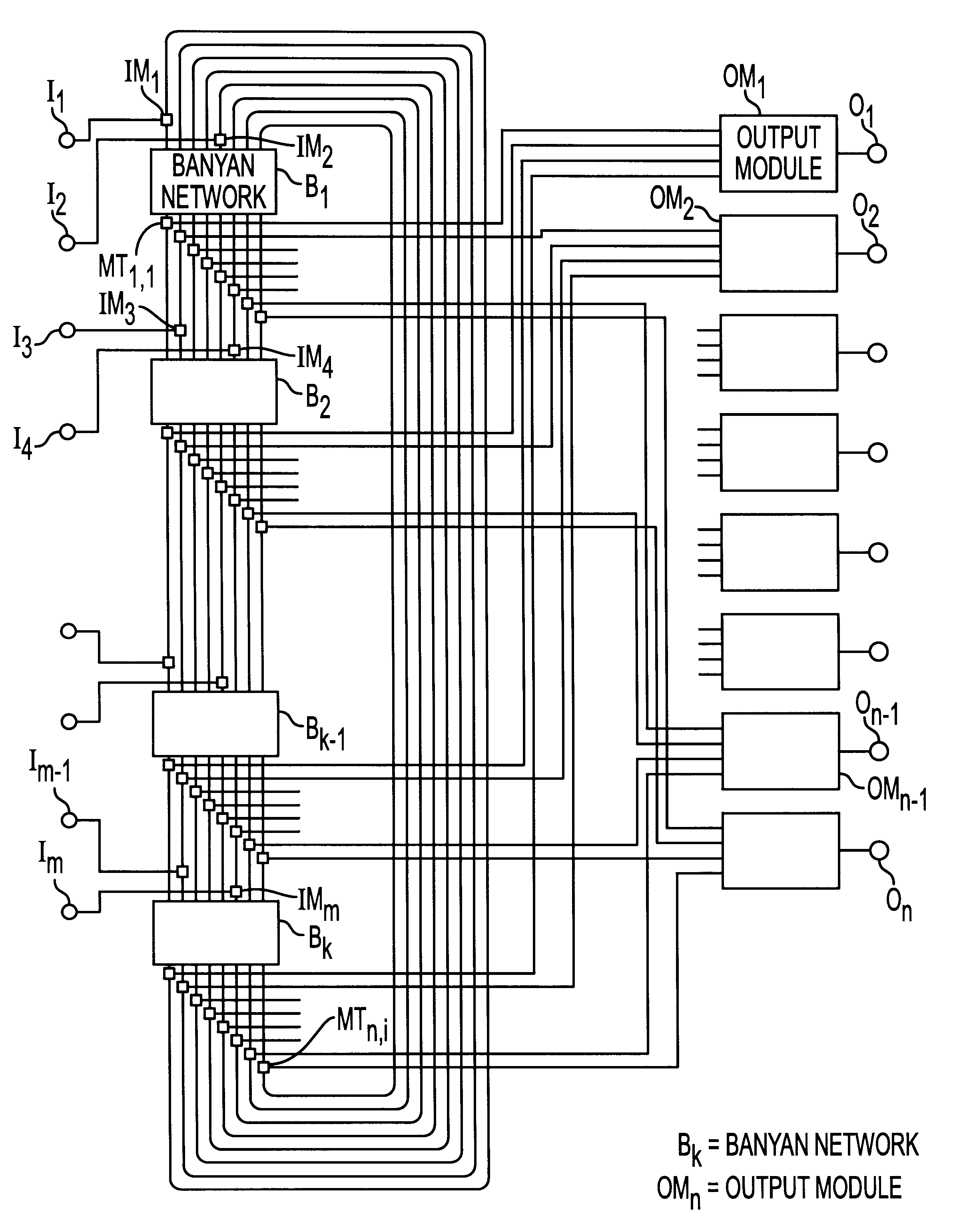
FIG. 6 is a block diagram showing an embodiment of the packet switching system according to the invention. The packet switching system comprises m input ports I.sub.h (h=1, 2, . . . , m) and m input modules IM.sub.h (h=1, 2, . . . , m), said input ports I.sub.h are connected to said input modules IM.sub.h. In the present embodiment, first two input ports I.sub.1 and I.sub.2 are connected to a first input module IM.sub.1, and a second input module IM.sub.2, respectively, the second two input ports I.sub.3 and I.sub.4 are connected to a third input module IM.sub.3 and a fourth input module IM.sub.2, respectively, and so on. The packet switching system further comprises k Banyan neworks B.sub.i (i=1, 2, . . . , k) each of which includes n outputs, nxi misroute tag check parts MT.sub.h,i and n output modules OM.sub.j (j=1, 2, . . . , n) each connected to respective output ports O.sub.j. In the embodiment shown in FIG. 6, it is assumed that m=n=8 and k=4, but these numbers may be set to ...


PUM


Abstract

In a system for switching high-capacity and variable length packets from m input ports to n output ports, k Banyan networks are connected into a ring by means of at least n parallel lines, said input ports are connected to inputs of said Banyan networks in a dispersed manner by means of m input modules, misroute tag check parts are connected to outputs of said Banyan networks as well as to inputs of n output modules whose outputs are connected to said output ports. Each of plural unit switches constituting a Banyan network is constructed such that when an input packet cannot be sent to a desired output, the relevant packet is outputted to a non-occupied output of the relevant Banyan network. When the misroute tag check part finds that the misroute tag is set, the relevant packet is sent to a next stage Banyan network, but when the misroute check tag is not set, the relevant packet is outputted to an output module connected to a desired output. The input module stores a packet from the input port and a packet from a misroute tag check part and sends one of these packets selectively to a succeeding Banyan network.

Description

1. Field of the InventionThe invention relates to a system for switching high-capacity and variable length packets from plural input ports to plural output ports.2. Related Art StatementA common bus system is currently used in most major IP(internet protocol) routers and has been used in almost all commercially available IP routers. FIG. 1 shows diagrammatically a packet switch of the common bus system. Each of plural input ports gets or acquires a right of using a common bus according to the round robin method and sends or broadcasts a packet on to the common bus. Each of plural outputs ports receives a broadcast packet addressed to the relevant output port. Therefore, in order to make a packet loss within the router to be zero, an operation speed of the common bus should be not lower than a value represented by (a transmission speed of each ports).times.(the number of the ports).The common bus system has advantages that variable-length packets can be exchanged and the number of ci...

Claims


Application Information

Patent Timeline
Patent Type & Authority Patents(United States)
IPC IPC(8): H04L12/56H04L12/70H04L12/931
CPCH04L49/25H04L49/102H04L49/1507H04L49/205H04L49/3009H04L49/3018
Inventor SAITO, TADAOAIDA, HITOSHIAOKI, TERUMASA
Owner THE UNIV OF TOKYO
Why Eureka
Try Eureka