Vehicle seat construction

a technology for vehicle seats and seat frames, which is applied in the field of vehicle seat construction, can solve the problems of difficult to determine the vertical position of the fixing attachments, irksome and time-consuming installation work of child seats, and preventing smooth installation of child seats

Inactive Publication Date: 2002-11-12
MITSUBISHI MOTORS CORP +1
View PDF19 Cites 37 Cited by
  • Summary
  • Abstract
  • Description
  • Claims
  • Application Information

AI Technical Summary

Benefits of technology

To achieve the above-described object, the present invention, in one aspect thereof, provides a vehicle seat construction comprising a vehicle seat main body having a seat cushion and a seatback; a reinforcement member secured on one of a frame of the vehicle seat main body and a floor on which the vehicle seat main body is mounted; an anchor member fixed on the reinforcement member for releasable engagement with a connector portion of a child seat; and a guide portion arranged in the reinforcement member such that the connector portion of the child seat is guided to the anchor member. In another aspect of the present invention, there is also provided a vehicle seat construction comprising a vehicle seat main body to be arranged in a vehicle; a guide portion for guiding a connector portion of a child seat to be mounted on the vehicle seat main body; an anchor member arranged for releasable engagement with the connector portion of the child seat guided by the guide portion; and a reinforcement member reinforcing the anchor member at a location thereof where the anchor member is attached. In a further aspect of the present invention, there is also provided a vehicle seat construction comprising a vehicle seat main body to be arranged in a vehicle; and a guide portion for guiding a connector portion of a child seat, said child seat being to be mounted on said vehicle seat main body, to an anchor member reinforced at a portion thereof where said anchor member is arranged such that said connector portion is brought into engagement with said anchor member. As described above, the reinforcement member is secured on the frame of the vehicle seat main body or on the floor, and the anchor bar is fixed on the reinforcement member. The anchor bar is hence provided with improved rigidity, thereby making it possible to minimize a displacement of the anchor bar in the event of a collision of a vehicle. Further, it is no longer required to apply beforehand substantial reinforcement to the frame or the like of the seat cushion. In addition, the anchor bar is provided with the guide portion which serves to guide the connector portion of the child seat to the anchor bar, so that the attachment of the child seat to the vehicle seat main body can be performed with extreme ease.
The plate may extend onto the guide surface. According to this preferred embodiment, the resin-made plate functions as a guide upon insertion of the connector portion, thereby facilitating the insertion of the connector portion of the child seat.

Problems solved by technology

With this method, however, the installation work of a child seat is irksome and time-consuming.
However, the arrangement of the anchor bar as mentioned above, that is, between the rear portions of both side frames of the frame of the seat cushion, said frames extending in the longitudinal direction of the vehicle, actually results in hiding of the anchor bar between a rear portion of the seat cushion and a lower portion of the seatback.
This makes it difficult to determine the vertical positions of the fixing attachments of the child seat upon its installation, thereby preventing smooth installation of the child seat.
In the event of a collision of the vehicle, the child seat is caused to move so that the anchor bar with which the child seat is in engagement is also caused to under go a large displacement.

Method used


Image

  • Vehicle seat construction
  • Vehicle seat construction
  • Vehicle seat construction

Examples


second embodiment

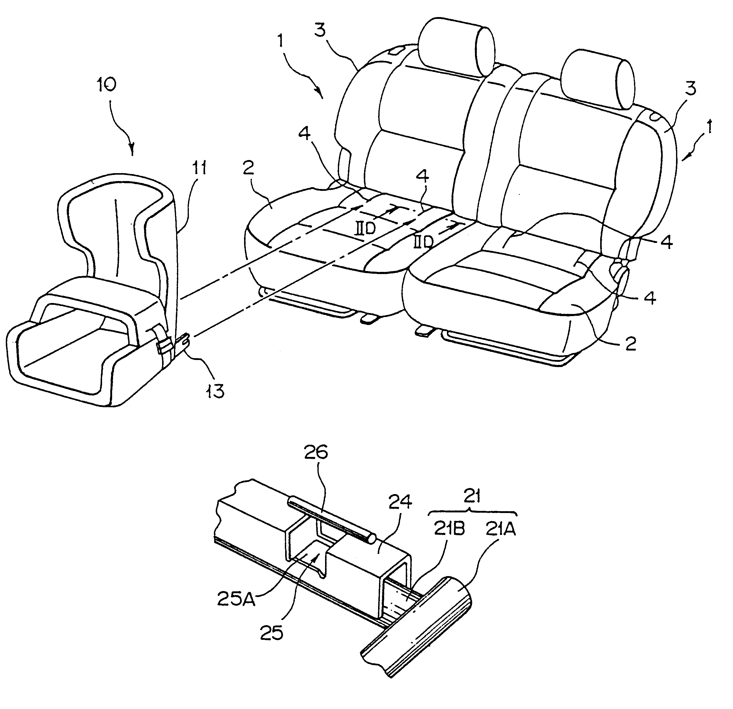
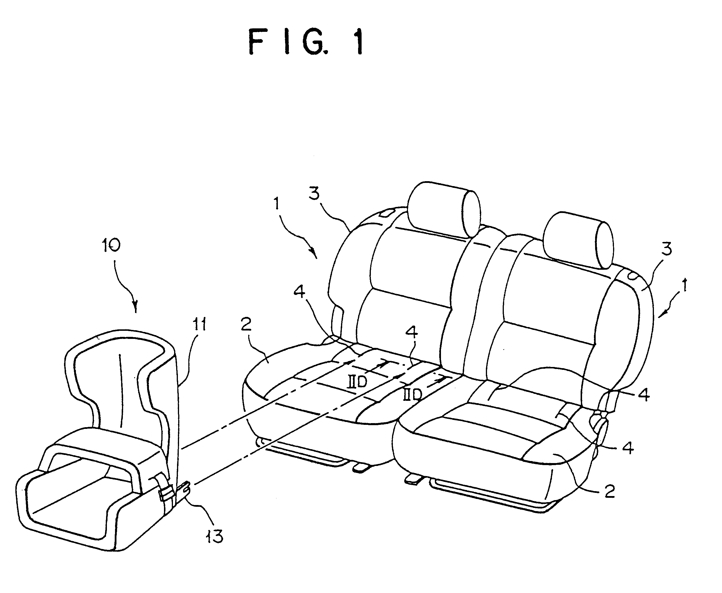
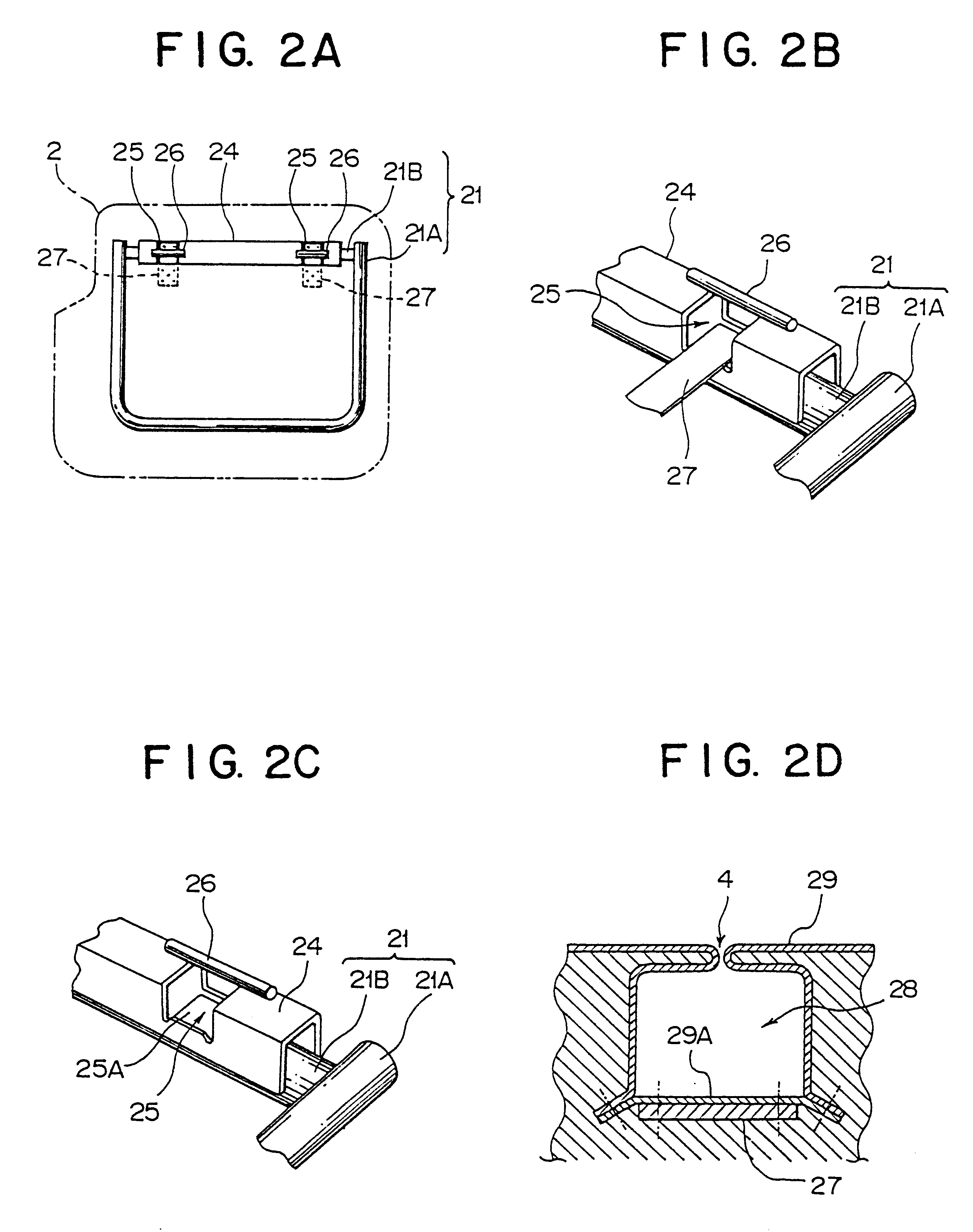
On an upper portion of the frame 21B laterally extending in a rear portion of the cushion frame 21, a reinforcement member 24 is secured, for example, by welding. It is to be noted that a member to which the reinforcement member 24 is secured is not limited to the cushion frame 21 and can be, for example, a laterally-extending frame (not shown) of the seatback or a vehicle floor on which the vehicle seat main body is to be mounted. An embodiment in which the reinforcement member 24 is secured on the vehicle floor will be described as the second embodiment subsequently herein. Referring next to FIG. 2A, the reinforcement member 24 is provided at two locations thereof with guide portions 25 so that they are apart from each other with a predetermined distance there between. On an upper portion of the reinforcement member 24, anchor bars 26 are fixed, for example, by welding such that the guide portions are located underneath the corresponding anchor bars 26.

Reference will next be had t...

first embodiment

As is illustrated in FIG. 4A, each seat main body 1 which constitutes, for example, a second seat is mounted on a vehicle floor 50. Further, as is shown in FIGS. 4A, 4B and 5, the reinforcement member 24 is secured by welding on the vehicle floor 50 in a vicinity of a location corresponding to a rear end of a seat cushion 2. As in the first embodiment, this reinforcement member 24 is provided with guide portions 25 at two locations apart from each other with a predetermined distance therebetween. On an upper portion of the reinforcement member 24, anchor bars 26 are fixed, for example, by-welding such that the corresponding guide portions 25 are located underneath the anchor bars 26.

Similarly to the first embodiment described above, each of the guide portions 25 arranged in the reinforcement member 24 has a guide surface 25A underneath the corresponding anchor bar 26 such that the corresponding connector portion 13 of the child seat 10 can be guided to the anchor bar 26. Each guide ...


PUM


Abstract

A vehicle seat construction includes a reinforcement member, which is secured on a frame of a vehicle seat main body, and anchor bars fixed on the reinforcement member such that connector portions of a child seat can be brought into releasable engagement with the anchor bars, respectively. The vehicle seat main body is provided with a seat cushion and a seatback. The anchor bars are fixed on upper portions of the reinforcement member, respectively, such that guide portions for guiding the corresponding connector portions of the child seat to the associated anchor bars are located below the anchor bars.

Description

a) Field of the InventionThis invention relates to a vehicle seat construction which facilitates fastening of a child seat onto a vehicle seat main body provided with a seat cushion and a seatback.b) Description of the Related ArtWhen driving with a child, it has been a conventional practice from the viewpoint of safety to fix a child seat on a vehicle seat and to keep him or her sitting there. As a method for fixing the child seat on the vehicle seat, it is possible to use, for example, a seatbelt which is arranged with the vehicle seat. With this method, however, the installation work of a child seat is irksome and time-consuming.To permit easy and quick installation of a child seat, a method has been proposed. According to this method, an anchor bar is arranged on a frame of a vehicle seat main body, and attachment members of a child seat are brought into engagement with the anchor bar. Described specifically, this method features that, as is disclosed in JP 11-198695 A, an ancho...

Claims


Application Information

Patent Timeline
Patent Type & Authority Patents(United States)
IPC IPC(8): B60N2/26B60N2/28B60R22/30B60N2/90
CPCB60N2/2821B60N2/2839B60N2/286B60N2/2893B60N2/289B60R22/30
Inventor HAYASHI, TAKEHITOMIZUNO, KOJIKUTOMI, SHINGOKODANI, YASUSHIMATSUOKA, TAKESHI
Owner MITSUBISHI MOTORS CORP
Why Eureka
Try Eureka