Capacitive physical quantity sensor

Inactive Publication Date: 2002-11-19
DENSO CORP
View PDF11 Cites 51 Cited by
  • Summary
  • Abstract
  • Description
  • Claims
  • Application Information

AI Technical Summary

Problems solved by technology

If these signals are out of phase, the sensor may erroneously operate or the accuracy of the sensor output may decrease because of mutual clock noises.

Method used


Image

  • Capacitive physical quantity sensor
  • Capacitive physical quantity sensor
  • Capacitive physical quantity sensor

Examples


Embodiment Construction

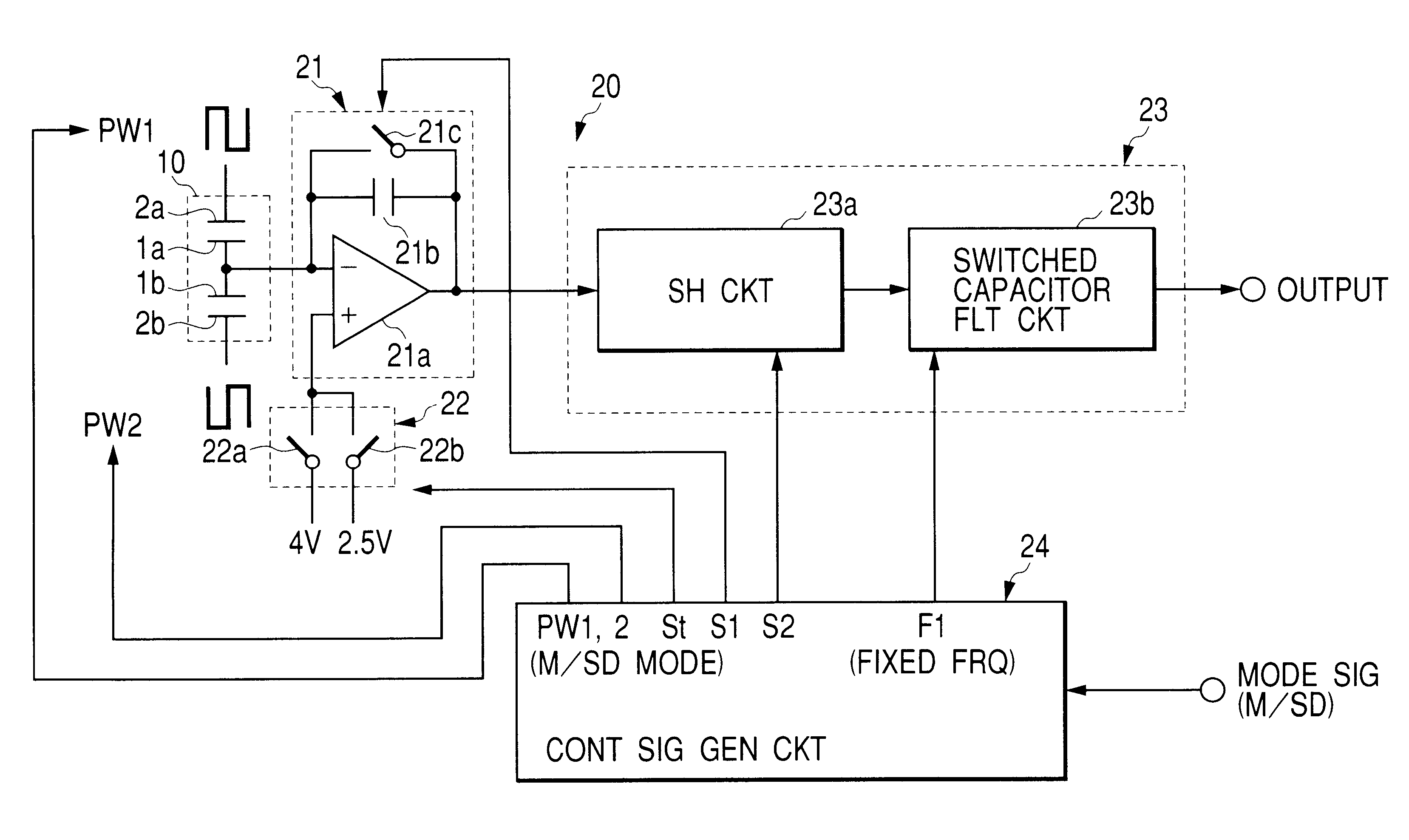
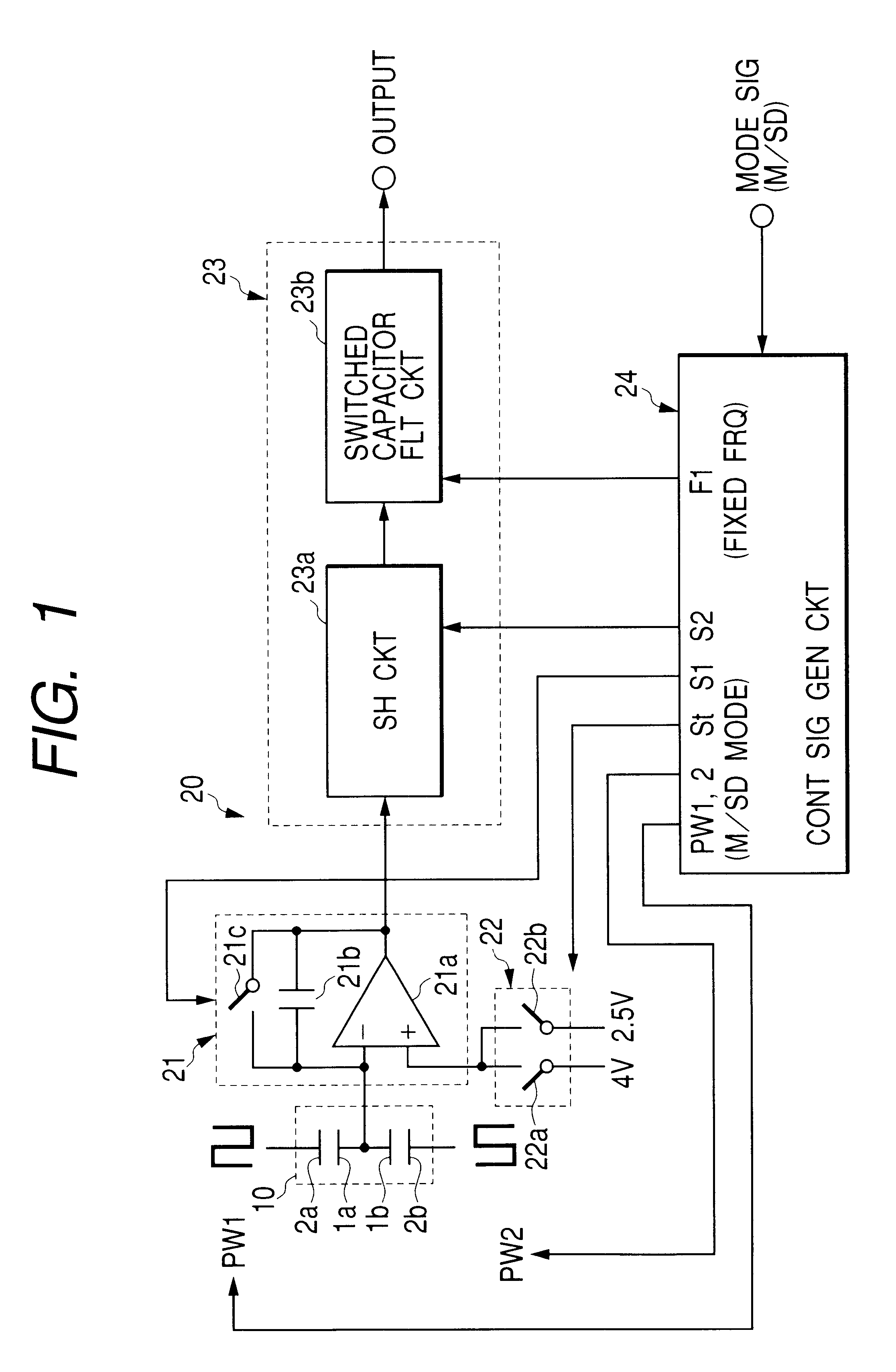
FIG. 1 shows a block diagram of a capacitor type of acceleration sensor including a capacitive physical quantity sensor according to the first embodiment of the present invention.

The acceleration sensor includes a sensor element 10 having movable electrodes 1a and 1b and fixed electrodes 2a and 2b, and a detection circuit 20 for detecting acceleration on the basis of a variation in the difference capacitance in the sensor element 10.

The sensor element 10 has a bridge structure (not shown) on a substrate (not shown) for detecting acceleration. One ends of the movable electrodes 1a and 1b are fixed to the bridge structure, and the fixed electrode 2a and 2b are fixed on the substrate as to face the movable electrodes 1a and 1b. In this embodiment, two movable electrodes 1a and 1b are provided. However, only one movable electrode may be provided and commonly used between a pair of fixed electrodes 2a and 2b.

The movable electrodes 1a and the fixed electrode 2a and the movable electrode 1...


PUM


Abstract

The clock signal for the sample and hold circuit for sampling the C-V conversion circuit output generated by the control signal generation circuit is different in period from the clock signal for switched capacitor filter circuit for filtering the sample and hold circuit output such that the clock signal for the switched capacitor filter circuit is unchanged in period between the measuring and self-diagnostic modes.

Description

1. Field of the InventionThis invention relates to a capacitive physical quantity sensor.2. Description of the Prior ArtAn acceleration sensor using a capacitive physical quantity sensor for detecting acceleration thereto is known. Recent acceleration sensors require a filter circuit in the signal processing circuit provided thereto for processing the signal from the sensor portion. Moreover, the filter circuit is required to have a low cutoff frequency so as to provide a low frequency range (for example, 10 to 10 KHz). This is because the acceleration signal is required to have a frequency range from zero (dc) to hundreds Hz, but a resonance frequency of the structure of the sensor exists at from hundreds to thousands Hz. This resonance frequency component should be removed. For this, a switched capacitor filter circuit (SFC circuit) is used. Moreover, the switched capacitor filter needs a relatively small area in the signal processing circuit and easily provides a low frequency ra...

Claims


Application Information

Patent Timeline
IPC IPC(8): G01P21/00G01P15/125G01L25/00G01L1/14
CPCG01P15/125G01P21/00
Inventor AOYAMA, SEIKIYAMAUCHI, SHIGENORI
Owner DENSO CORP
Why Eureka
Try Eureka