Transfer for four-wheel drive vehicle

a four-wheel drive, vehicle technology, applied in mechanical equipment, transportation and packaging, gearing, etc., can solve the problems of increased weight and cost of transfer, complicated structure, etc., and achieve the effect of low cost, light weight and simple structur

Inactive Publication Date: 2002-11-26
AISIN AI CO LTD
View PDF11 Cites 10 Cited by
  • Summary
  • Abstract
  • Description
  • Claims
  • Application Information

AI Technical Summary

Benefits of technology

With the conventional transfer of the kind described above, the two functions required by the transfer (namely the speed-reducing function and center differential function) are implemented by two planetary gear mechanisms. The result is a complicated structure as well as an increase in the weight and cost of the transfer.
Accordingly, an object of the present invention is to provide a transfer, the structure of which is simplified, for a four-wheel drive vehicle.

Problems solved by technology

The result is a complicated structure as well as an increase in the weight and cost of the transfer.

Method used


Image

  • Transfer for four-wheel drive vehicle
  • Transfer for four-wheel drive vehicle
  • Transfer for four-wheel drive vehicle

Examples


first embodiment

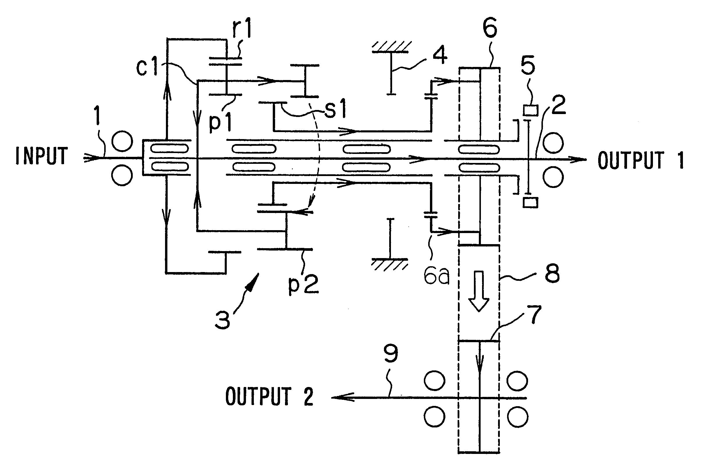
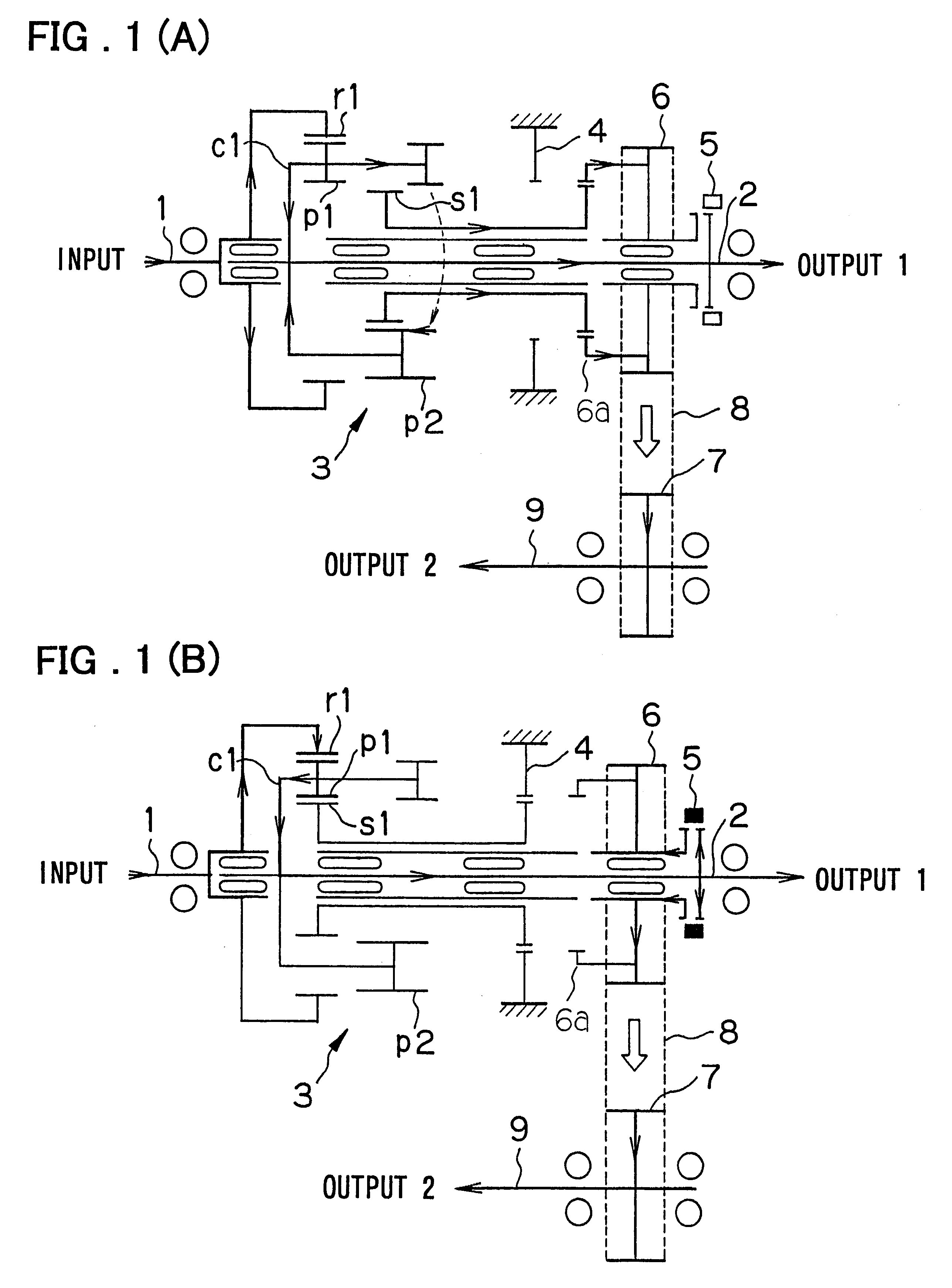
FIGS. 1A and 1B are gear train diagrams of a transfer for a four-wheel drive vehicle according to the present invention, in which FIG. 1A illustrates the state of operation of the transfer in the high position and FIG. 2B the state of operation of t he transfer in the low position.

As shown in FIGS. 1A and 1B, a first output shaft 2 is disposed coaxially with respect to an input shaft 1 to which torque from a transmission (main transmission) is applied, and a second output shaft 9 is disposed in parallel with the first output shaft 2. A ring gear r1 which co-rotates (i.e., rotates in unison) with the input shaft 1 is disposed radially onternally of the first output shaft 2. A first end of the first pinion p1 is meshed with the ring gear r1. The first pinion pi extends toward the other side axially of the first output shaft 2 and has teeth at both axial ends thereof that are spaced apart from each other in the axial direction. A second pinion p2 is in mesh with a second end of the fir...

second embodiment

the invention will now be described. In principle, only the difference between this embodiment as the first embodiment set forth above will be discussed. Reference should be had to the foregoing embodiment for an understanding of components and functions that are common to both embodiments.

FIG. 5 is a gear train diagram showing the principal components of a transfer according to the second embodiment of the present invention. In this embodiment, the second pinion p2 has an axial length greater than that of the first pinion p1 and has teeth at both axial ends thereof that are spaced apart from each other in the axial direction. The second end of the second pinion p2 is capable of being meshed with the sun gear s1, and the first end of the second pinion p2 extends toward the left side in FIG. 5 (i.e., toward the side of the main transmission). The first pinion p1 and the first end of the second pinion p2 are in mesh at all times on the side of the main transmission.

The present inventi...


PUM


Abstract

A transfer for a four-wheel drive vehicle of simplified structure in which speed-reducing and center differential functions are implemented by a single planetary gear set includes an input shaft; a first output shaft disposed coaxially with respect to the input shaft; a ring gear which co-rotates with the input shaft; a first pinion meshed with the ring gear; a second pinion in mesh with the first pinion at all times; a carrier for axially supporting the first and second pinions; a sun gear which, by being slid, selectively meshes with the first pinion or the second pinion; a brake for locking the sun gear when the sun gear and the first pinion mesh (the low position of the transfer); a driving gear which meshes with the sun gear when the sun gear and the second pinion mesh (the high position of the transfer); a sleeve mounted on the first output shaft and shifted for engaging the driving gear with the first output shaft in the direction of rotation; a second output shaft disposed in parallel with the first output shaft; and a driven gear which co-rotates with the second output shaft and to which torque is transmitted from the driving gear via a chain.

Description

This invention relates a transfer for a four-wheel drive vehicle and, more particularly, to a planetary-gear-type transfer for a four-wheel drive vehicle.FIG. 6 is a diagram of a gear train in a transfer for a four-wheel drive vehicle according to the prior art. This transfer includes a first planetary gear mechanism 60, i.e., an auxiliary speed-change unit, for exerting a speed-reducing effect, and a second planetary gear mechanism 61, i.e., a center differential, for implementing a center differential function.SUMMARY OF THE DISCLOSUREIn the course of investigations toward the present invention the following problem has been encountered in the art.With the conventional transfer of the kind described above, the two functions required by the transfer (namely the speed-reducing function and center differential function) are implemented by two planetary gear mechanisms. The result is a complicated structure as well as an increase in the weight and cost of the transfer.Accordingly, an ...

Claims


Application Information

Patent Timeline
Patent Type & Authority Patents(United States)
IPC IPC(8): B60K17/346B60K17/344B60K17/35
CPCB60K17/3467
Inventor INOUE, TORU
Owner AISIN AI CO LTD
Why Eureka
Try Eureka