Printing unit

a printing unit and printing technology, applied in printing presses, rotary letterpress machines, printing, etc., can solve the problem of relatively complicated design structur

Inactive Publication Date: 2002-12-17
MANROLAND WEB SYST
View PDF17 Cites 82 Cited by
  • Summary
  • Abstract
  • Description
  • Claims
  • Application Information

AI Technical Summary

Problems solved by technology

This design has a relativ

Method used


Image

  • Printing unit
  • Printing unit
  • Printing unit

Examples


Embodiment Construction

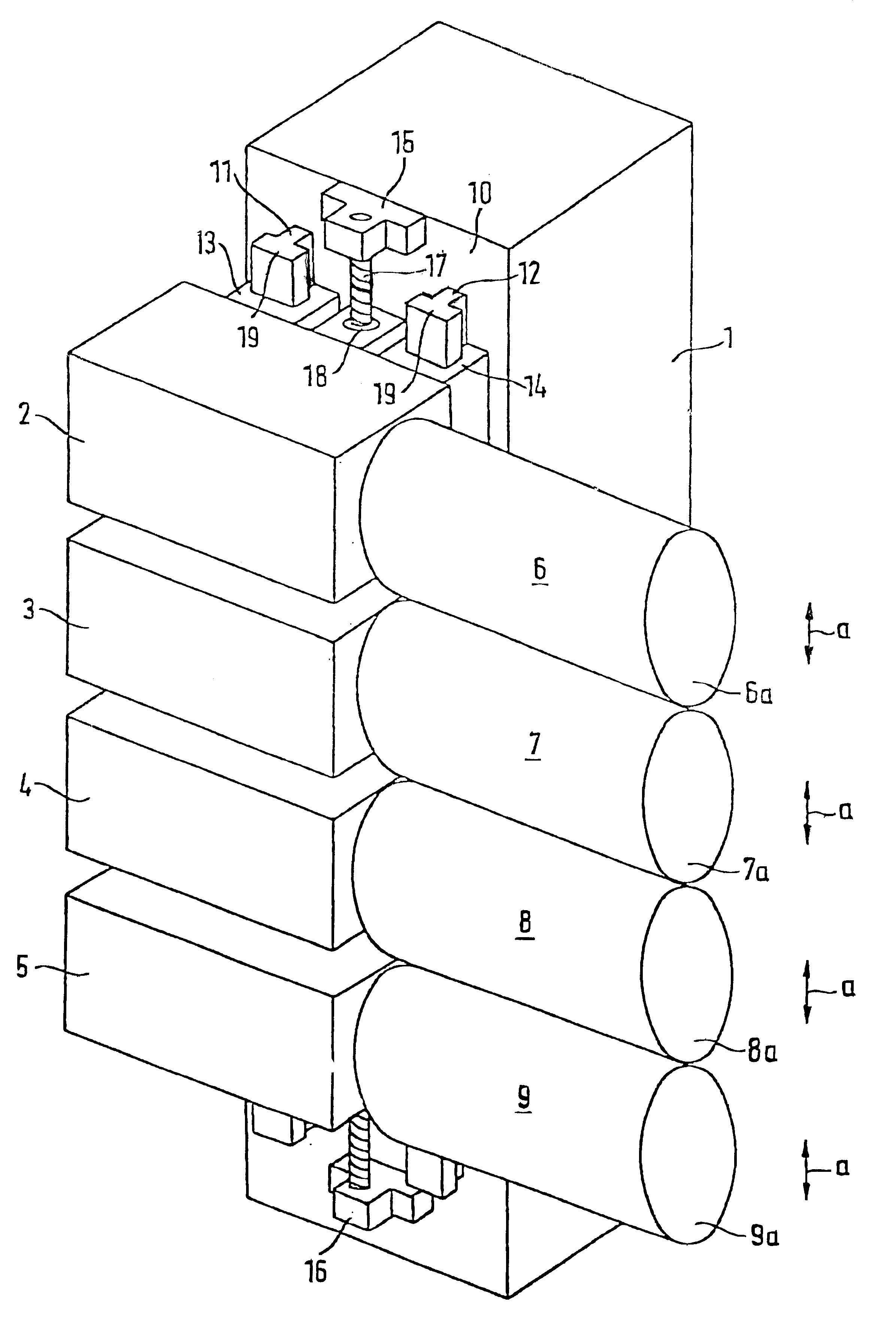
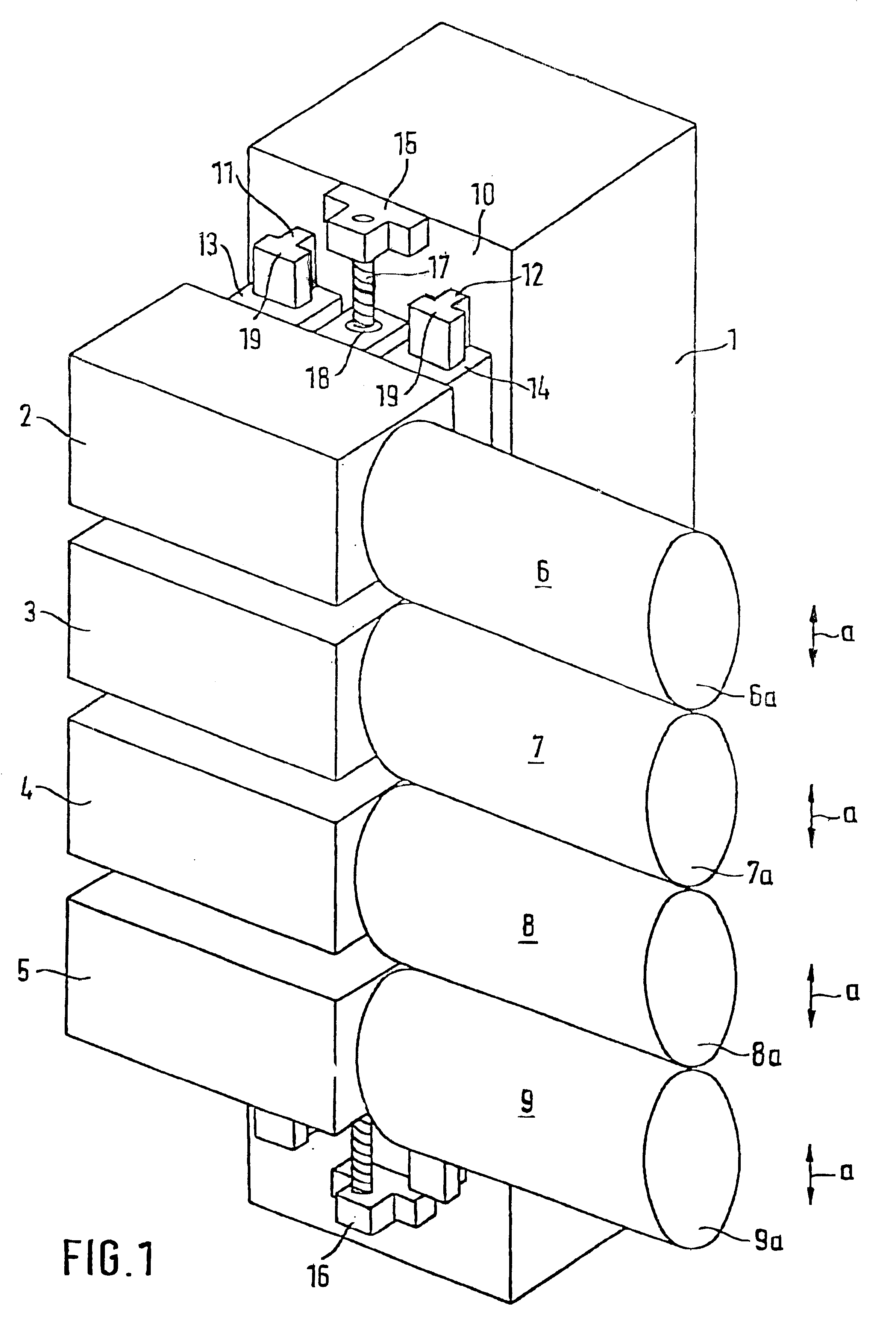
Referring now to FIG. 1 the printing of the present invention has a load bearing wall 1, on which identical carriages 2 to 5 are guided. Each carriage 2 to 5 carries a printing-unit cylinder 6 to 9 and accommodates a drive motor (not illustrated) for its printing-unit cylinder. In this case, the load bearing wall 1 is arranged laterally beside the ends 6a to 9a of the printing-unit cylinders 6 to 9. In order to guide the carriages 2 to 5, one wall side or surface 10 of the load bearing wall 1, which runs perpendicular to an imaginary plane drawn through the ends 6a to 9a of the printing-unit cylinders 6 to 9, bears two guide elements 11, 12, on which appropriately shaped sliding blocks 13, 14 of the carriages, e.g. 2, can slide. The guide elements 11, 12 are designed here as rails and are fixed to the wall surface 10 of the load bearing wall over their entire length. In order to prevent the carriages 2 to 5 from lifting off the load bearing wall 1, a form-fitting carriage guide syst...


PUM


Abstract

A printing unit is provided for a web fed printing machine having at least two cylinders where at least one of the cylinders is adjustable with respect to another of the cylinders; a machine frame having at least one load bearing wall arranged laterally beside an end of the cylinders; a drive motor corresponding to each cylinder; at least one guide element operably attached to the load bearing wall at a surface of the load bearing wall that runs perpendicular to a plane through the end faces of the cylinders; and a plurality of carriages attached to the guide element. At least one of the cylinders is connected to the carriages so that a distance from another of the cylinders can be adjusted.

Description

1. Field of the InventionThe invention relates to a printing unit for a web-fed rotary printing machine, having at least two printing-unit cylinders each having its own drive motor and of which at least one can be set linearly at a distance from the other by means of a carriage guide system on the machine frame.2. Description of the Related ArtGerman Patent Application No. 195 34 651.3 discloses a printing unit of this type which has two frame walls running parallel to the end faces of the printing-unit cylinders. The printing-unit cylinders can be fitted with sleeves of different diameter, so that the length of the printed image can be changed. A carriage is provided on the frame walls on both sides of the cylinder to mount the ends of a printing-unit cylinder. The carriages can be adjusted by working cylinders operated with a pressurized means. This design has a relatively complicated structure.The object of the present invention is to provide a simple, cost-effective structure fo...

Claims


Application Information

Patent Timeline
IPC IPC(8): B41F13/30B41F13/00B41F13/24B41F13/44B41F13/26B41F13/38
CPCB41F13/30B41F13/44
Inventor GOTTLING, JOSEFDAUER, HORST
Owner MANROLAND WEB SYST
Why Eureka
Try Eureka