Liquid applicator implement

a technology of liquid applicator and implement, which is applied in the direction of ink reservoir pens, printing, writing accessories, etc., can solve the problems of implement that does not give satisfactory writing or application trace or image on the support, and achieves the effect of printing very fast and writing quickly

Inactive Publication Date: 2002-12-24
DATAPRINT R KAUFMANN
View PDF106 Cites 57 Cited by
  • Summary
  • Abstract
  • Description
  • Claims
  • Application Information

AI Technical Summary

Benefits of technology

Accordingly even large amounts of liquid can be applied to the support in a short time with the implemen

Problems solved by technology

In that way the implement of FIG. 11 is extremely leak-proof in spite of a very large supply of liquid.
In practical operation that has the result from time to t

Method used


Image

  • Liquid applicator implement
  • Liquid applicator implement
  • Liquid applicator implement

Examples


Embodiment Construction

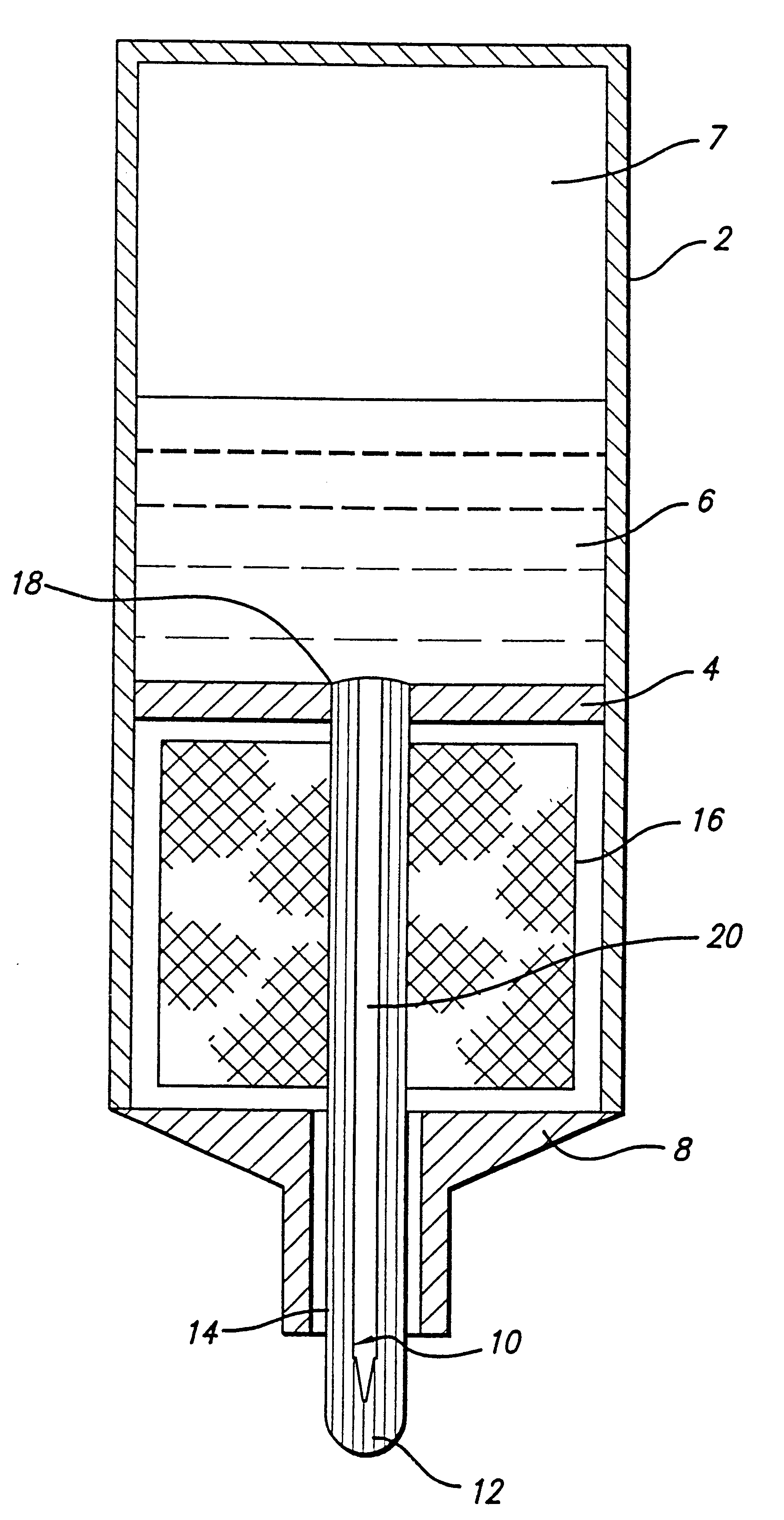
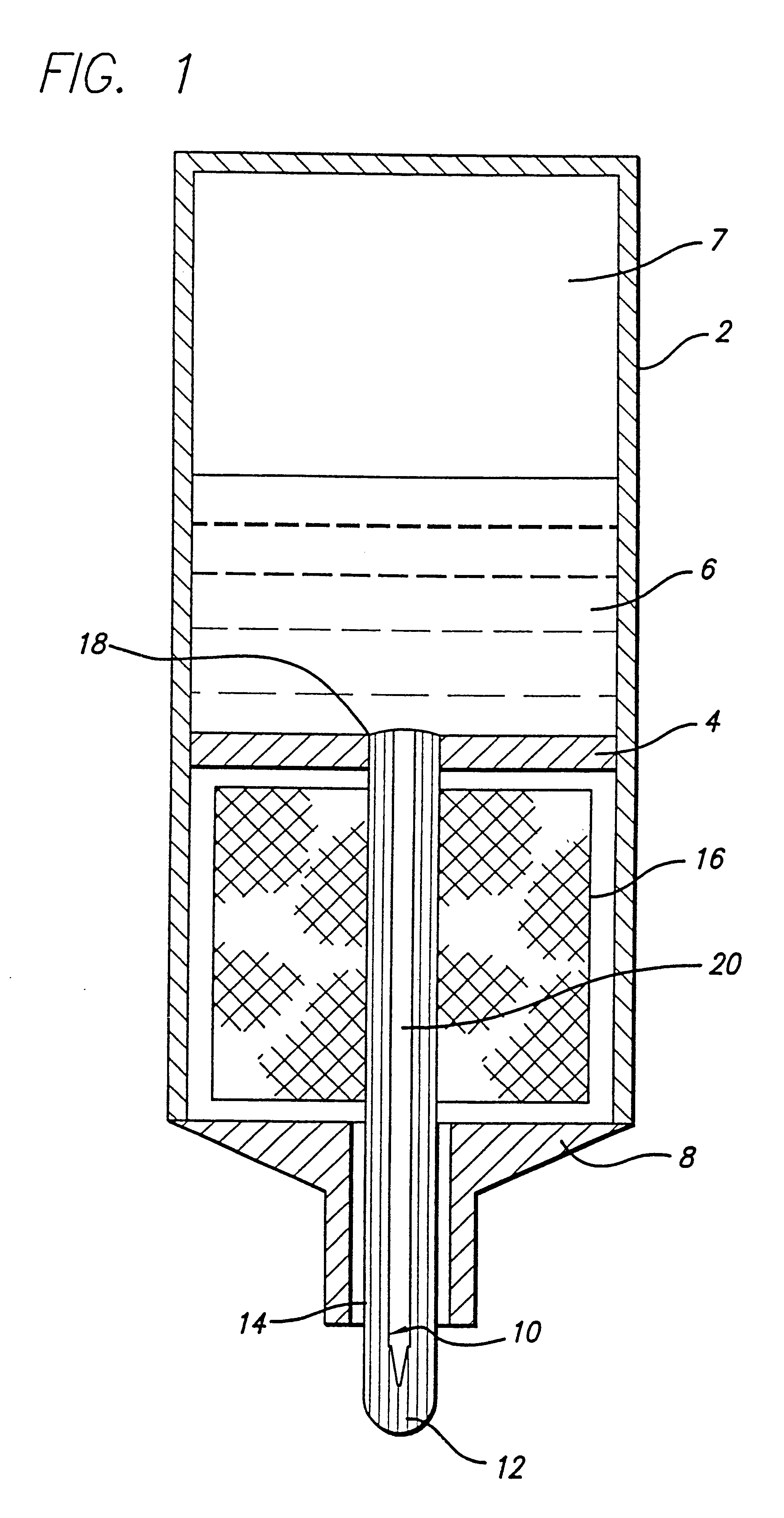
Referring to FIG. 1, a writing implement to the operated by hand comprises a casing 2 with a divider wall. Above the divider wall 4 there is a supply of freely movable liquid 6, for example writing ink, above which there is in turn an air volume 7.

Within casing 2 above divider wall 4 there is space for accommodating a large volume of liquid 6 (10 ml or more).

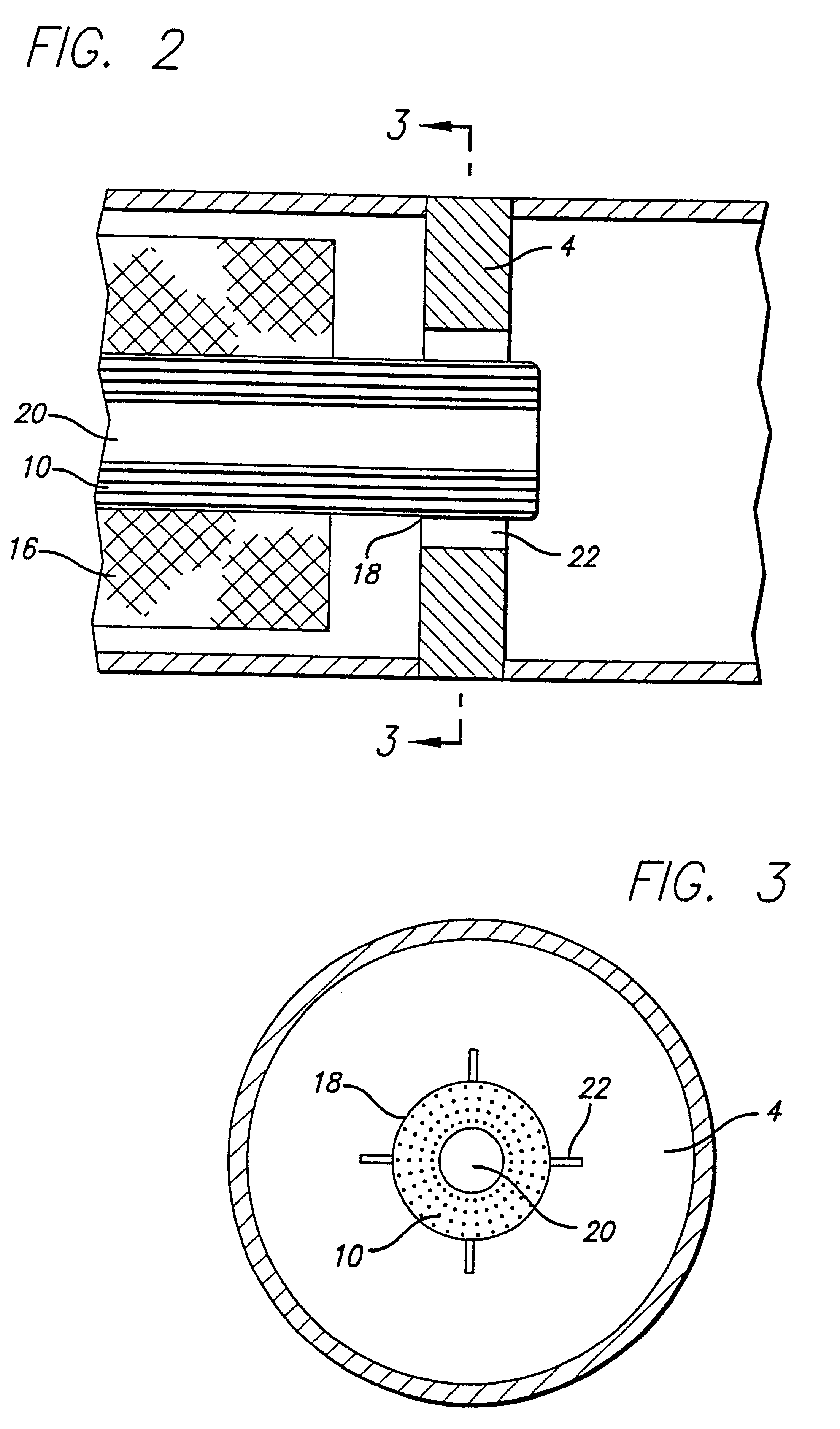
At the bottom the casing 2 terminates in a front portion 8 in which a wick 10 is held, the wick 10 terminating in an applicator or writing tip 12. Extending laterally beside the wick 10 through the front portion 8 is at least one vent bore 14 or a vent passage. The wick 10 extends through a storage means 16 of capillary material which is disposed in the casing 2 below the divider wall 4, into an opening 18 which is provided in the divider wall 4, and which it completely fills. The storage means 16 embraces the wick 10 in such a way that it is at least in part in direct contact with the wick 10. As in the FIG. 11 implement the ca...


PUM


Abstract

A liquid applicator implement includes a container for freely movable liquid (6), a capillary storage (16) for temporarily receiving liquid upon a change in air pressure and/or temperature of the environment, an applicator element (12) and a capillary air inlet for compensation in respect of liquid taken from the container. A passage (20) for conveying the liquid entirely or partially bridges over the distance between the container with the liquid (6) and the applicator element (12). The passage is not directly in communication with the storage (16) and it is of lower capillarity than the storage (16).

Description

1. Field of InventionThe invention concerns an implement for applying a liquid to a support by means of an applicator element.2. Description of the Related ArtAn implement is known from DE 41 15 682 and will now be described with reference to FIG. 11.Provided within a casing 2 is a divider wall 4, above which a supply of freely movable liquid 6 is accommodated in the casing. Above the liquid 6 is a volume of air 7 which increasingly replaces the liquid as it is discharged.At its lower end the casing 2 has a tapering front portion 8 with a through opening in which is held a wick 10 terminating in a writing tip 12 serving as an applicator element. Extending laterally beside the wick 10 through the front portion 8 is a vent bore 14. A storage means 16 of capillary material which closely embraces the wick 10 is accommodated in the space between the front portion 8 and the divider wall 4. The wick 10 completely fills an opening 18 provided in the divider wall 4 so that only the wick 10 p...

Claims


Application Information

Patent Timeline
IPC IPC(8): B43K8/00B43K7/10B43K7/00B43K8/04B05C17/00B43K8/02
CPCB43K7/10B43K8/04
Inventor KAUFMANN, RAINER
Owner DATAPRINT R KAUFMANN
Why Eureka
Try Eureka