Method for configuring and assigning channels for a wireless network

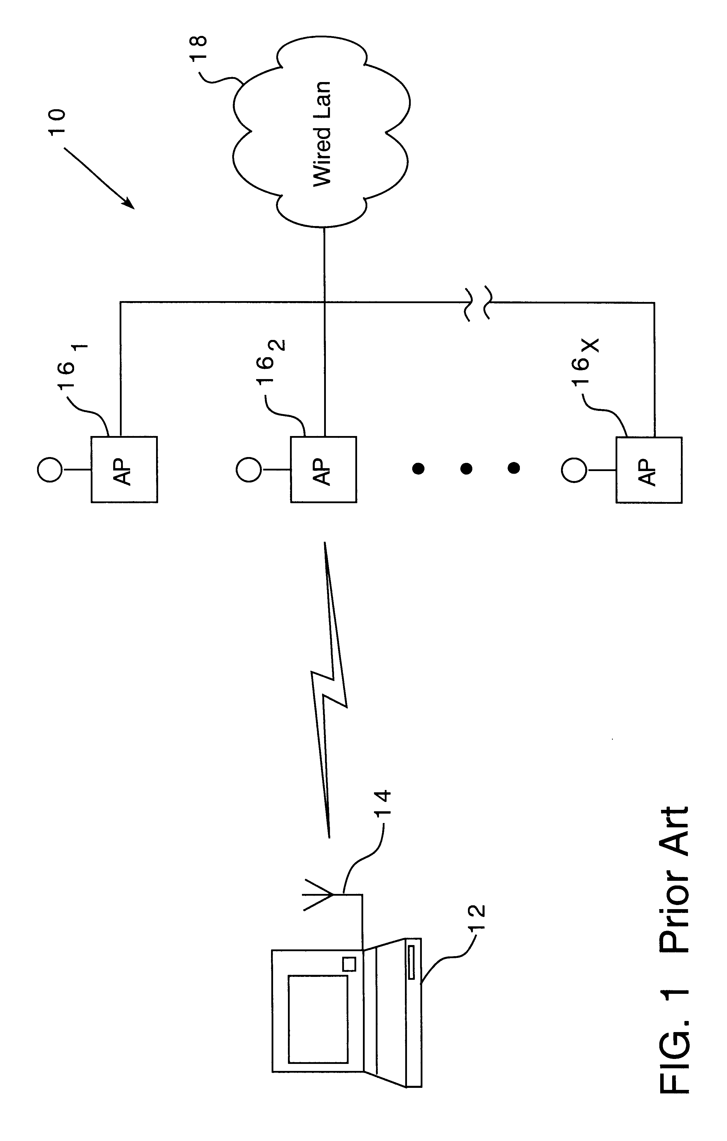
a wireless network and channel assignment technology, applied in the field of wireless communication networks, can solve the problems of metal, the greatest obstacle to the wireless transmission between the nas 14 and the aps 16, and the undesirable signal interference between the aps 16, so as to minimize the overlap of coverage, minimize the cost, and maximize the effect of network performan

Inactive Publication Date: 2003-01-07
CARNEGIE MELLON UNIV
View PDF11 Cites 135 Cited by
  • Summary
  • Abstract
  • Description
  • Claims
  • Application Information

AI Technical Summary

Benefits of technology

According to another embodiment, the present invention is directed to a method for assigning channels for access points for a network providing wireless communications coverage for an environment, including assigning a weight indicative of overlapping coverage for each pair of access points having overlapping coverage, and assigning a channel to each of the access points based on certain sums of the weights to minimize coverage overlap between access points operating at the same channel.
According to another embodiment, the present invention is directed to a method for configuring access points of a network providing wireless communications coverage for an environment, including determining a coverage radius of an access point at certain locations within the environment, determining an average coverage radius of the access points for the environment based on the determined coverage radii, positioning the access points at locations within the env

Problems solved by technology

Implementing a WLAN 10 inside a building complicates the design because the layout and construction of the building affect the wireless signal transmissions between the NAs 14 and the APs 16.
In addition, the greatest obstacle to the wireless transmissions between the NAs 14 and APs 16 commonly found in all building envi

Method used


Image

  • Method for configuring and assigning channels for a wireless network
  • Method for configuring and assigning channels for a wireless network
  • Method for configuring and assigning channels for a wireless network

Examples


example 2

FIGS. 5 and 6 illustrate another embodiment of the present invention, in which a 145 wireless network is to be implemented to provide wireless coverage for a number of contiguous floors of a multi-floor building 50 where the width of the floors is no greater than R2. According to one embodiment, as illustrated in FIG. 5, a first AP 16.sub.1 may be placed on a second floor of the contiguous floors of the building 50 at the intersection of an edge of the building 50 and the line B--B' bisecting the building 50 lengthwise. The position of the first AP 16.sub.1 may be adjusted such as, for example, by moving the first AP 16.sub.1 along the bisecting line B--B' such that the coverage area of the first AP 16.sub.1 on a first floor of the building 50 immediately below the second floor, having an approximate coverage radius of R', extends to two corners (A, A') of the building on the first floor. It should be noted that the reference here and elsewhere to "first" and "second" floors does no...

example 3

FIGS. 7-10 illustrate another embodiment of the present invention, in which a wireless network is implemented on one floor of a building 50 whose width is greater than R2. The described method for establishing the location of the APs 16 may be followed, for example, where the building 50 has one story, where only one floor of a multi-floor building 50 requires wireless coverage, or where certain floors of a multi-floor building are to be treated separately.

According to one embodiment, as illustrated in FIG. 7, a first AP 16.sub.1 may be located at the distance R from a corner A of the building 50 along a line extending from the corner, such as on a 45.degree. angle. The location of the first AP 16.sub.1, may be adjusted such that its coverage area extends to the corner of the building 50. According to one embodiment, the position of the first AP 16.sub.1 may be adjusted by moving the first AP 16.sub.1 along the line extending 45.degree. from the corner A of the building 50.

As illust...

example 4

FIGS. 11-15 illustrate another embodiment of the present invention, in which a wireless network is to be implemented on first and second contiguous floors of a building 50 where the width of the floors is greater than R2. As discussed hereinbefore, the reference to "first" and "second" floor does not necessarily refer to the first and second floors of the building, but rather any two floors of a multi-floor building.

According to one embodiment, as illustrated in FIG. 1 , a first AP 16.sub.1 may be located at a corner A of the building 50 on the second floor. A second AP 16.sub.2 may be located on the first floor at the distance D' from the corner of the building 50 along a line extending from the corner A, such as on a 45.degree. angle. The locations of the first and second APs 16.sub.1,2 may be adjusted to assure that the edges of the coverage areas on the first floor intersect at two sides of the building 50. In the illustrated embodiment, the coverage areas of the APs 16 for the ...


PUM


Abstract

A method for configuring access points of a network providing wireless communications coverage for an environment, including determining a coverage radius of an access point at certain locations within the environment, determining an average coverage radius of the access points for the environment based on the determined coverage radii, positioning the access points at locations within the indoor environment to provide continuous radio coverage for the environment based on the average coverage radii, assigning a weight indicative of overlapping coverage for each pair of access points having overlapping coverage, and assigning a channel to each of the access points based on certain sums of the weights to minimize coverage overlap between access points operating at the same channel.

Description

Not Applicable.Not Applicable.BACKGROUND OF INVENTION1. Field of InventionThe present invention is directed generally to wireless communication networks and, more particularly, to methods for configuring and assigning channels for wireless networks.2. Description of the BackgroundWireless local area networks (WLANs) were originally intended to allow wireless connections to a wired local area network (LAN), such as where premises wiring systems were nonexistent or inadequate to support conventional wired LANS. A block diagram of a typical WLAN 10 is illustrated in FIG. 1. The WLAN 10 includes a mobile device 12 including a network adapter (NA) 14, a number of access points (APs) 16.sub.1-x, and a wired LAN 18. The APs 16 are typically radio base stations, each mounted in a separate fixed position and connected to the wired LAN 18. The NA 14 communicates with the APs 16 by formatted wireless communication signals to provide an interface between the computing device 12 and the wired LA...

Claims


Application Information

Patent Timeline
IPC IPC(8): H04L12/28H04Q7/36H04W16/18H04W16/20
CPCH04W16/18H04W16/20H04W28/16H04W24/00
Inventor HILLS, ALEXANDER H.SCHLEGEL, JON P.
Owner CARNEGIE MELLON UNIV
Why Eureka
Try Eureka