Motorized lock for flaps or doors in motor vehicles, especially a lock for glove compartments

a technology for motor vehicles and flaps, applied in the field of motorized locks for flaps or doors of motor vehicles, can solve problems such as inapplicability

Inactive Publication Date: 2003-01-14
HUF HULSBECK & FURST GMBH & CO KG
View PDF14 Cites 28 Cited by
  • Summary
  • Abstract
  • Description
  • Claims
  • Application Information

AI Technical Summary

Problems solved by technology

Even though for locks of different kinds motor-driven closing and opening aids ar

Method used


Image

  • Motorized lock for flaps or doors in motor vehicles, especially a lock for glove compartments
  • Motorized lock for flaps or doors in motor vehicles, especially a lock for glove compartments
  • Motorized lock for flaps or doors in motor vehicles, especially a lock for glove compartments

Examples


Embodiment Construction

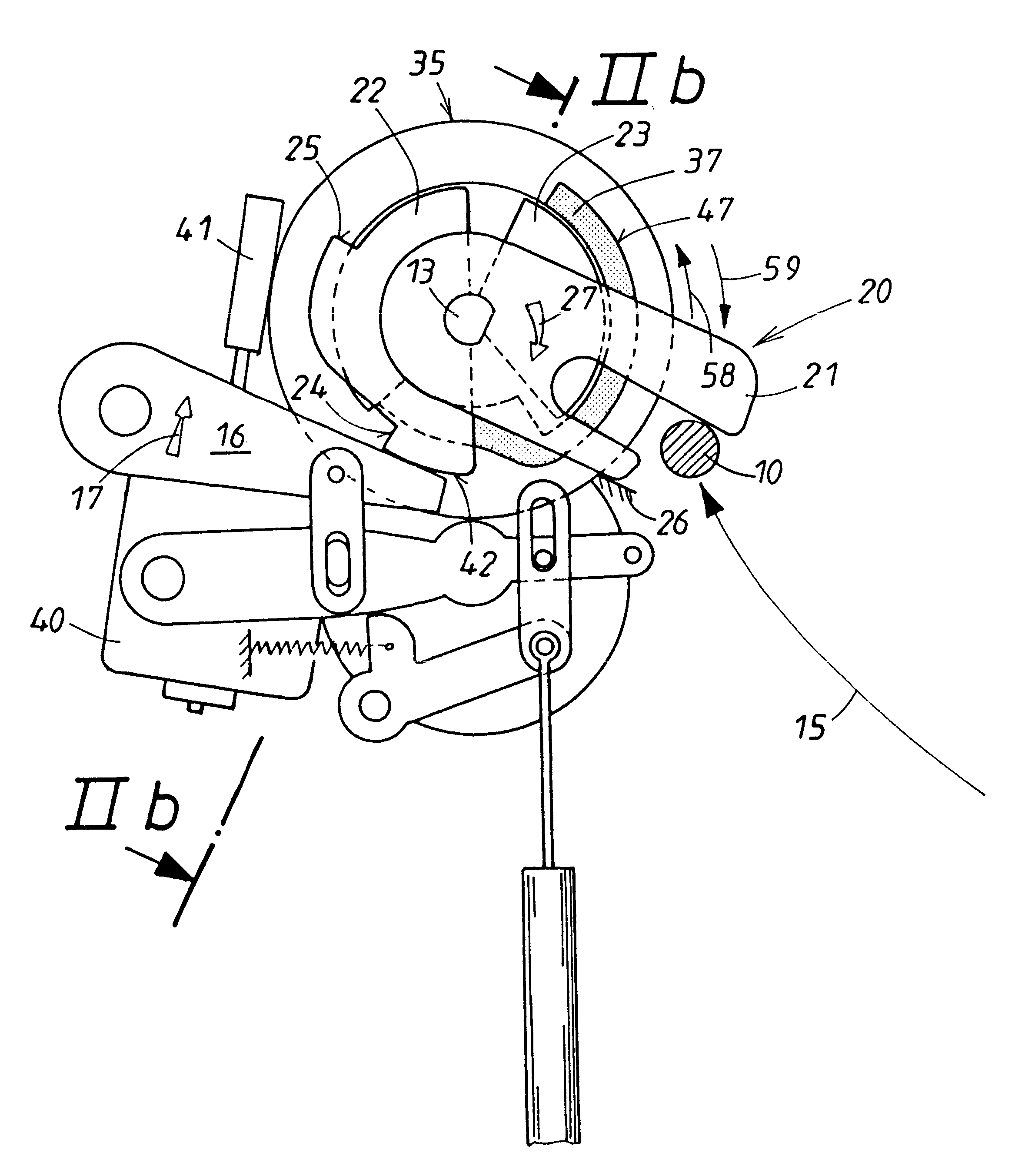
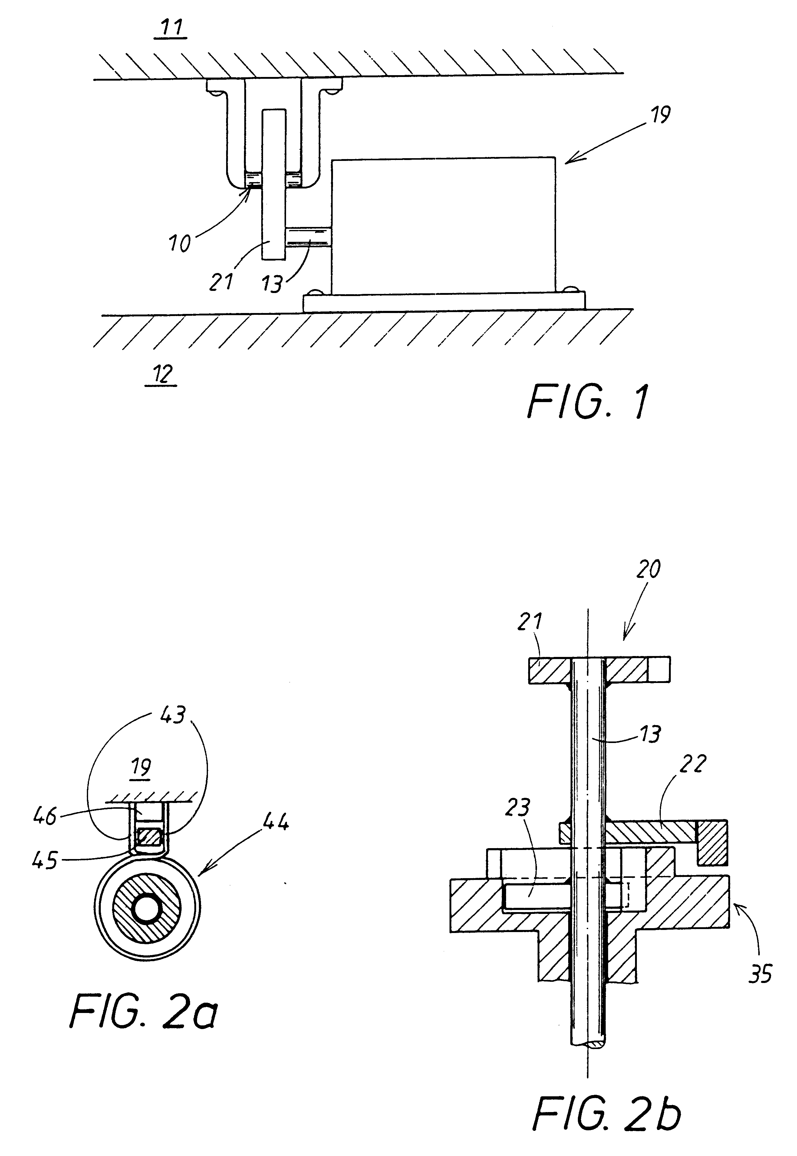
The lock illustrated in the Figures is used preferably for a flap which belongs to a glove compartment. Accordingly, in FIG. 1 the movable flap 11 and the stationary compartment rim 12 are illustrated schematically. In the present case the movable flap 11 supports the frame with a closing member 10, here in the form of a bolt with a round cross-section while the compartment rim 12 has a lock housing 19 from which the rotary latch 22 projects which cooperates with the closing member 10. It is understood that the lock parts 10, 19 can also be arranged mirror-symmetrically relative to the movable and stationary elements 11, 12 of the glove comfort and.

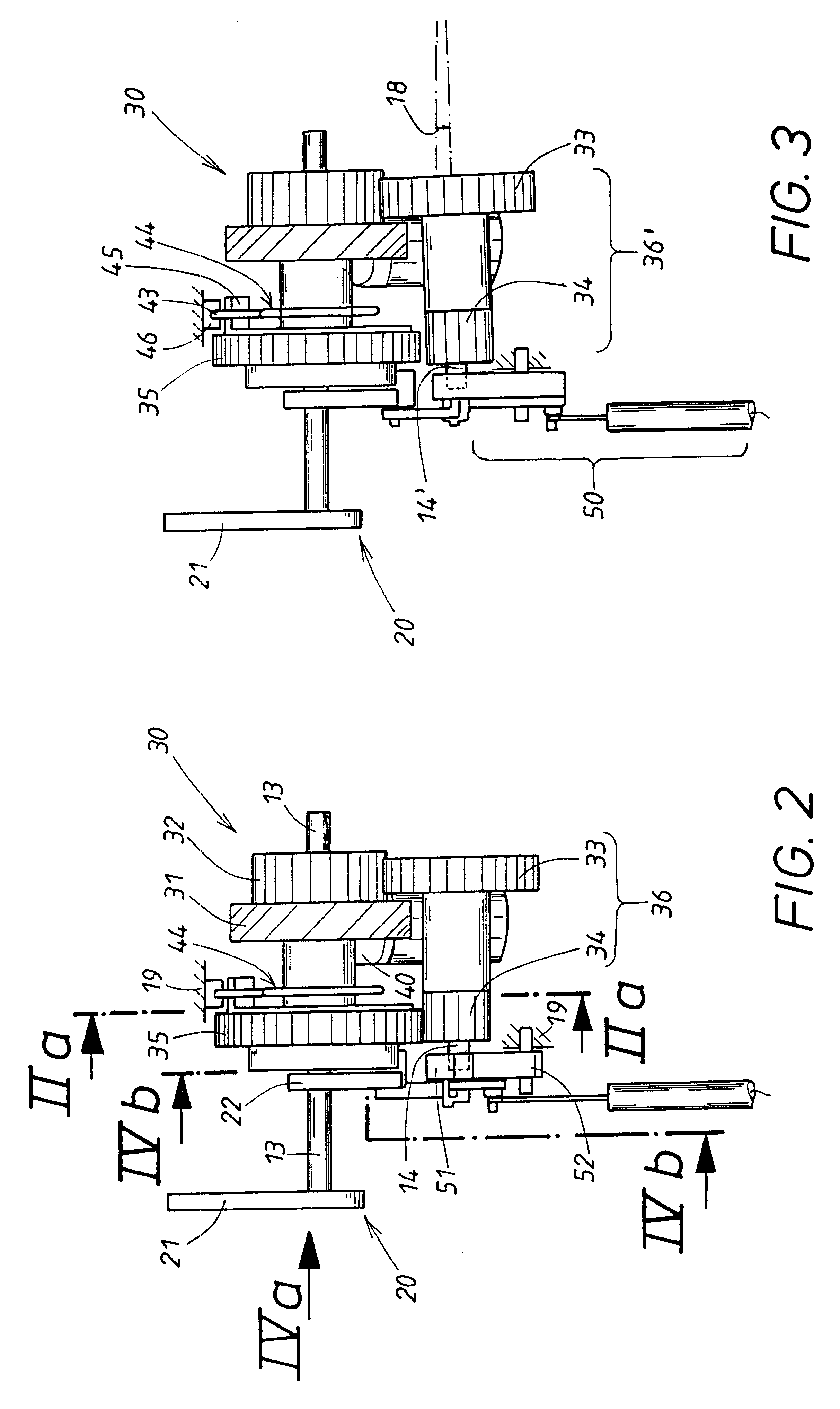
The most important lock parts provided in the lock housing 19 are illustrated in FIGS. 2 to 4b. In the lock housing 19 an axle shaft 13 is rotatably supported which forms a component unit 20 of several components 21 to 23 which are fixedly connected to one another. The component 20 is thus a part which is rotatable in its entirety and is ...


PUM


Abstract

The invention relates to a lock that can be used with a flap, comprising a rotary unit that is made up of a rotary spagnolet that interacts with a closing element (10) and a rotating latch (22). In order to improve operational performance, the rotary unit is provided with a rigid catch (23) that preferably has two counter shoulders running in opposite directions. The output member (35) of a motor (40)-driven gear mechanism is also provided with two corresponding counter shoulders. This enables the motor to provide assistance with closing and, optionally, opening, whereby the rotary unit can be guided in a closing, tilting direction or an opening, tilting direction until the flap is fully closed or opened. The motor (40) comprises a gear mechanism with a group of gears that can be displaced between an engaged position and a separated position. The detent pawl (16) which interacts with the rotating latch (22) is disabled in the separated position, should an emergency arise. When the flap is in a closed or open position, a free area exists between the shoulders and counter shoulders, enabling the flap to be moved manually.

Description

1. Field of the InventionThe invention relates to a motorized lock for flaps or doors of motor vehicles, especially a lock for a glove compartment.2. Description of the Related ArtThe motorized lock of the aforementioned kind has a rotary spagnolet in which, during closing of the flap, a locking member is inserted and rotates the rotary spagnolet out of an open pivot position, characterizing the open position of the flaps via a split position of the flap into a closed position determining the locked position of the flap, with a locking pawl having a rotating latch connected rotationally fixedly to the rotary spagnolet when the locking pawl is active and when the rotary unit, comprised of the rotary spagnolet and the rotating latch, has been transferred out of its open pivot position, with the flap in the open position, either into a pre-locking position determining the split position of the flap or into a closed pivot position defining the locked position of the flap.Even though for...

Claims


Application Information

Patent Timeline
IPC IPC(8): E05B65/12B60R25/01E05B47/00E05B65/19E05B65/32E05B81/20E05B83/30
CPCE05B83/30E05B81/20Y10T292/1082E05B83/28E05B81/06
Inventor SZABLEWSKI, PIOTRGEURDEN, ARMINMULLER, ULRICH
Owner HUF HULSBECK & FURST GMBH & CO KG
Why Eureka
Try Eureka