Asymmetric digital subscriber line methods suitable for long subscriber loops

a technology of digital subscriber lines and loops, applied in the field of communications, can solve the problems of limited data rate of such transmission, analog nature of old central office switches, and inability to provide a broad range of services, and achieve the effect of reducing the number of analog channels

Inactive Publication Date: 2003-01-14
MICROSEMI FREQUENCY & TIME
View PDF25 Cites 62 Cited by
  • Summary
  • Abstract
  • Description
  • Claims
  • Application Information

AI Technical Summary

Problems solved by technology

Older central office switches were analog in nature and were unable to provide a broad range of services.
Because of the 4 kHz constraint imposed by the A / D converter in the line circuit, the data rate of such transmission is limited and is typically 9.6 kbps.
With increasing deployment of, and consequently demand for, digital services it is clear that this bit rate is insufficient.
A stumbling block in specifying, or guaranteeing, a definite bit rate to a customer is the nature of the loop plant.
The essentially lowpass frequency response of subscriber cable limits the usable bandwidth and hence the bit rate.
In these loaded loops, the spectral region above 10 kHz is unusable for reliable transmission.
Heretofore, there has not been a completely satisfactory approach to providing DSL over long loops.
Further, there has not been a satisfactory approach to providing DSL over loaded loops.

Method used


Image

  • Asymmetric digital subscriber line methods suitable for long subscriber loops
  • Asymmetric digital subscriber line methods suitable for long subscriber loops
  • Asymmetric digital subscriber line methods suitable for long subscriber loops

Examples


Embodiment Construction

The invention and the various features and advantageous details thereof are explained more fully with reference to the nonlimiting embodiments that are illustrated in the accompanying drawings and detailed in the following description. Descriptions of well known components and processing techniques are omitted so as not to unnecessarily obscure the invention in detail. It should be understood, however, that the detailed description and the specific examples, while indicating preferred embodiments of the invention, are given by way of illustration only and not by way of limitation. Various substitutions, modifications, additions and / or rearrangements within the spirit and / or scope of the underlying inventive concept will become apparent to those skilled in the art from this detailed description.

Within this application several publications are referenced by superscripts composed of Arabic numerals within parentheses. Full citations for these, and other, publications may be found at th...


PUM


Abstract

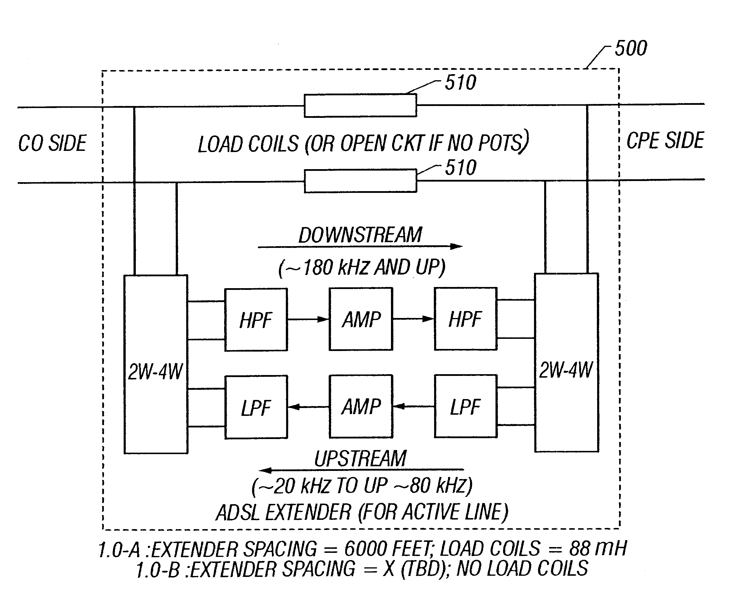
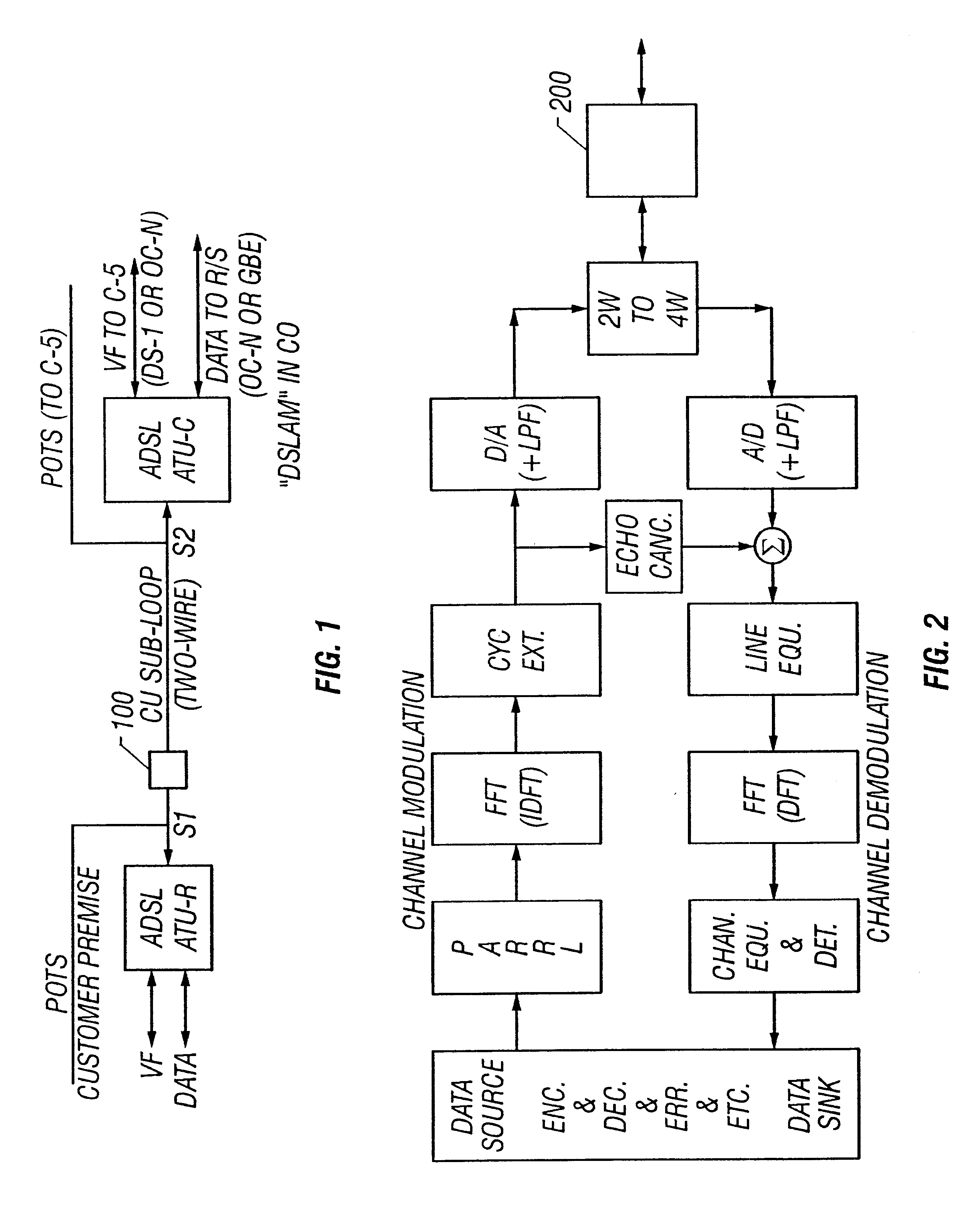
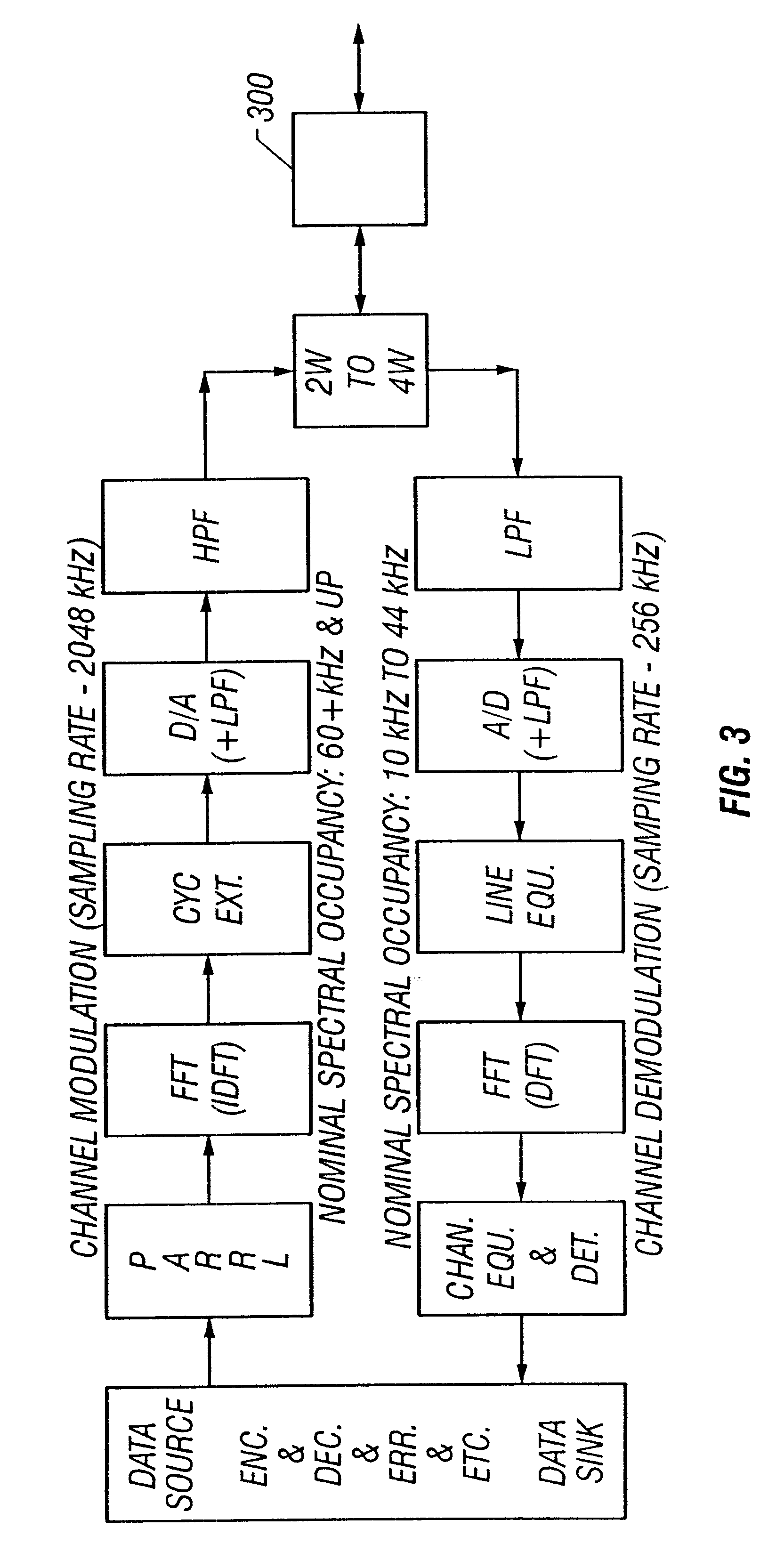
Systems and methods are described for asymmetric digital subscriber loops. A method includes utilizing a circuit having a first end and a second end, the circuit having a first amplification interface connecting the first end to the second end in a first direction, and a second amplification interface connecting the second end to the first end in a second direction; adapting the first amplification interface to provide a first gain adjustment as a function of a first attenuation of a first communication by a first direction impedance from the transmission medium while transmitting in the first direction, the first communication within a first frequency range over the transmission medium from the first end to the second end; and adapting the second amplification interface to provide a second gain adjustment as a function of a second attenuation of a second communication by a second direction impedance from the transmission medium while transmitting in the second direction, the second communication within a second frequency range over the transmission medium from the second end to said first end. An apparatus includes a modulator for transmitting a first communication, in a first direction over a transmission medium, the modulator operably coupled to a first amplification interface for providing a first gain adjustment, based on a first attenuation of the first communication in the first direction by a first direction impedance of the transmission medium; and a demodulator operably coupled to the modulator, for receiving a second communication, in a second direction over the transmission medium, the demodulator operably coupled to a second amplification interface for providing a second gain adjustment, based on a second attenuation of the second communication in the second direction by a second direction impedance of the transmission medium.

Description

1. Field of the InventionThe invention relates generally to the field of communications. More particularly, the invention relates to digital subscriber loop (DSL) communications. Specifically, a preferred implementation of the invention relates to extending the range of an asymmetric digital subscriber loop (ADSL). The invention thus relates to ADSL of the type that can be termed extended.2. Discussion of the Related ArtConventional telephony, often called plain old telephone service (POTS), is provided to customers over copper cable. This copper cable can be termed a subscriber loop or a subscriber line. Modern loop plant designs specify the use of 26-gauge cable for short to medium loop lengths with 24-gauge cable used to extend the range. Legacy loop plant includes cable of 22-gauge as well as 19-gauge.At the customer premises, a telephone set is typically connected to the cable. The other end of the cable is connected to a line circuit module in the service provider's central of...

Claims


Application Information

Patent Timeline
Patent Type & Authority Patents(United States)
IPC IPC(8): H04L5/02H04L5/14H04L27/26H04L25/22H04L25/20
CPCH04L5/023H04L5/143H04L27/2653H04L27/264H04L25/22H04L27/2654H04L27/26416
Inventor SHENOI, KISHANSQUADRITO, SANDROBOGARDUS, GARY
Owner MICROSEMI FREQUENCY & TIME
Why Eureka
Try Eureka