Horn switch for a steering wheel

a technology of horn switch and steering wheel, which is applied in the direction of pedestrian/occupant safety arrangement, transportation and packaging, and vehicular safety arrangement, etc., can solve the problems of connecting bolt falling, movable support member and movable contact being deformed, and adding time to the operation of fastening the connecting bol

Inactive Publication Date: 2003-01-21
TOYODA GOSEI CO LTD +1
View PDF15 Cites 39 Cited by
  • Summary
  • Abstract
  • Description
  • Claims
  • Application Information

AI Technical Summary

Benefits of technology

With the horn switch according to the invention, the connecting bolt is temporarily fixed to the stationary member before tightening. Therefore, a lower surface of the head is latched even if the connecting bolt becomes loose, thus eliminating the possibility of its falling.
With the horn switch thus constituted, it becomes unnecessary to arrange on the bag holder any nuts provided with threads for threading of the male threaded portions of the fastening bolts, thus reducing the man-hours required for manufacture of the bag holder and reducing or eliminating costs.

Problems solved by technology

Therefore, there is the possibility of the connecting bolt falling if it becomes loose.
In this case, the positioning projections get out of the positioning holes at other fastening locations of other connecting bolts to cause positional deviation, which takes time to correct, adding time to the operation of fastening the connecting bolts.
Therefore, there is no possibility of the movable support member and the movable contact being deformed.
That is, in the case of directly mounting a small horn switch on a large steering wheel body, the ring section of the steering wheel body creates interference, making assembly difficult.

Method used


Image

  • Horn switch for a steering wheel
  • Horn switch for a steering wheel
  • Horn switch for a steering wheel

Examples


Embodiment Construction

The invention will be described below with respect to embodiments shown in the drawings. In addition, the invention is not limited to these embodiments and is intended to include all modifications or equivalents thereof.

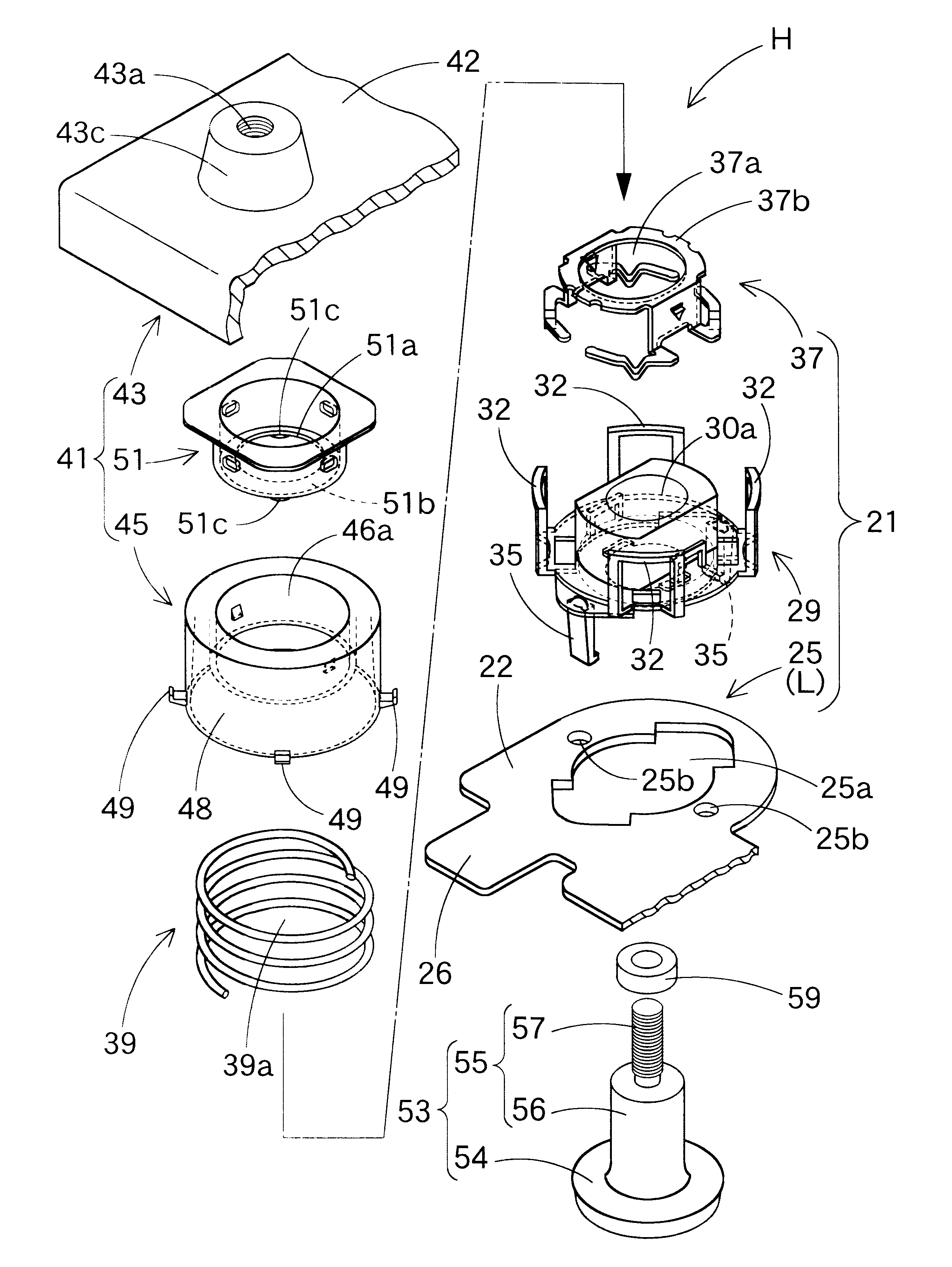
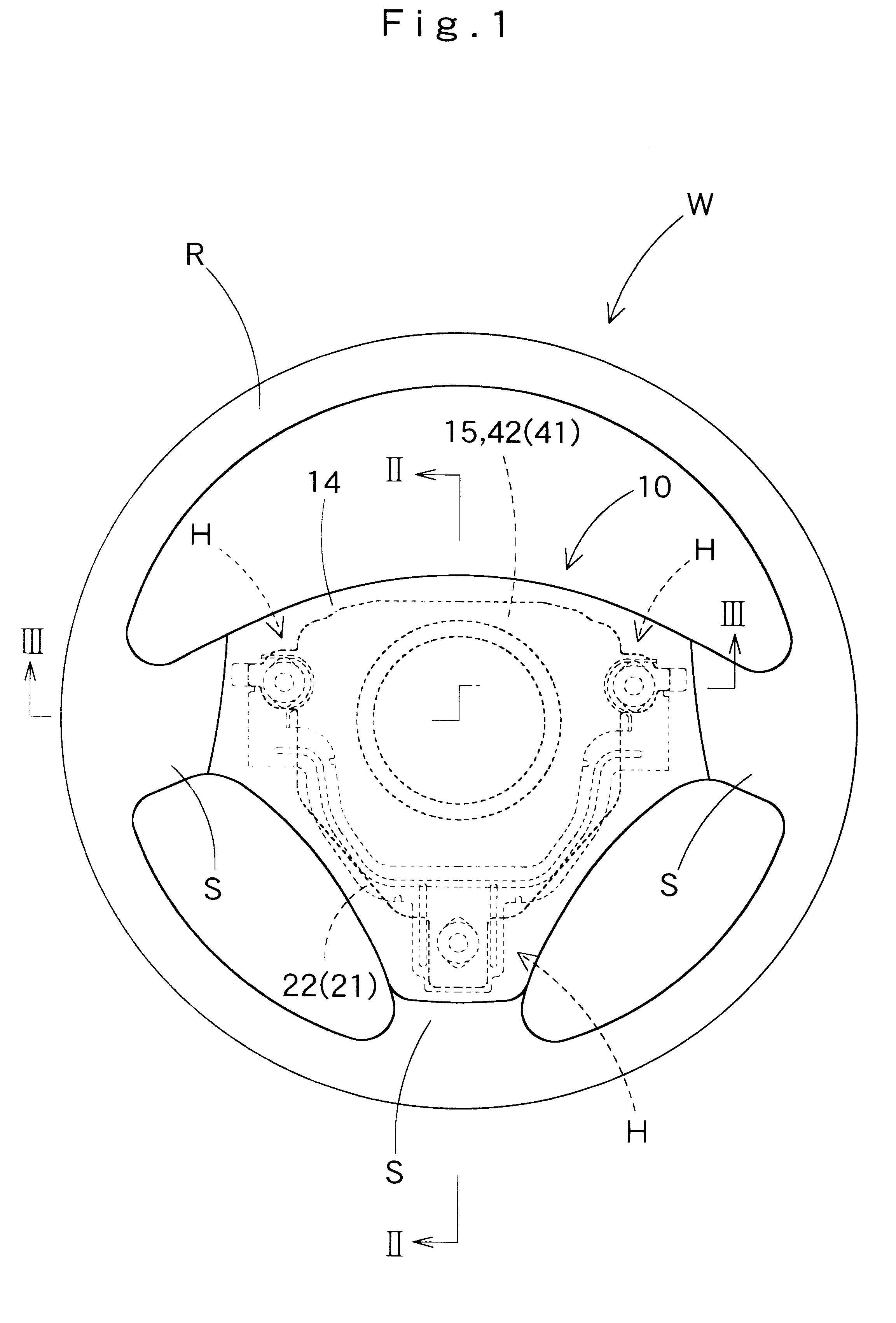
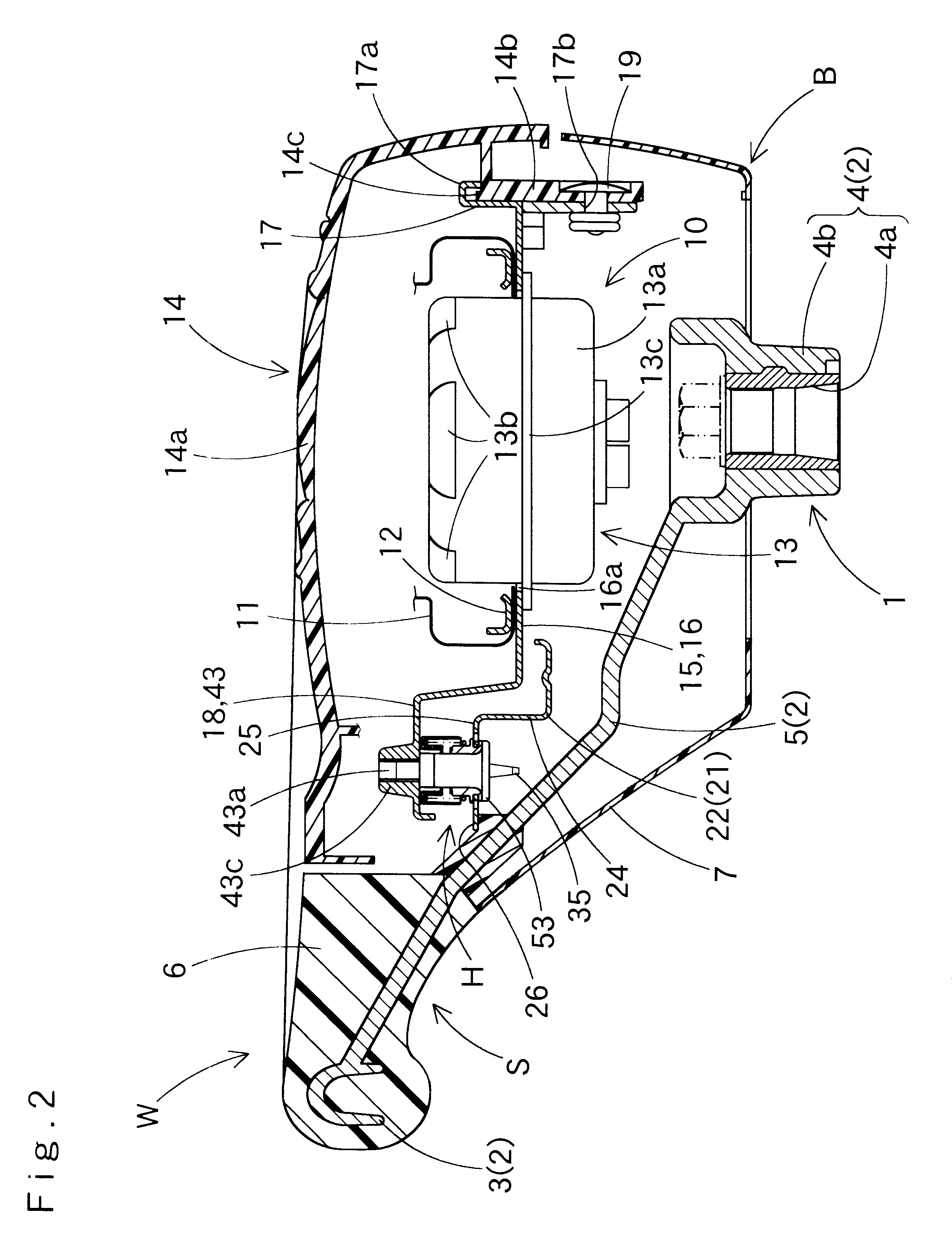
A steering wheel W including a horn switch H according to an embodiment of the invention comprises, as shown in FIGS. 1 to 3, a torus-shaped ring section R, a boss section B disposed centrally with respect to the ring section R, and three spoke sections S connecting the ring section R and the boss section B to each other. Also, the steering wheel W comprises other constituent parts, that is, a steering wheel body 1, an airbag device 10 arranged above the boss section B, and the horn switches H. The horn switches H are connected to the steering wheel body 1 that supports the airbag device 10.

The steering wheel body 1 indicates a section separate from the airbag device 10 and the horn switches H. The steering wheel body 1 comprises a core metal 2 arranged to connect re...


PUM


Abstract

A horn switch includes a stationary member, a movable member, a spring and a connecting bolt. The stationary member has a stationary contact and is supported on a steering wheel body The movable member has a movable contact and is arranged above the stationary member. The connecting bolt allows downward movements of the movable member and prescribes a distance of the movable contact from the stationary contact. The connecting bolt is provided with a head and a shank. The head abuts against an underside of the stationary member. The shank extends upward from the head to be fastened to a threaded hole in the movable member. Prior to fastening, the connecting bolt is temporarily fixed to the stationary member by latch legs. The latch legs latch a lower surface of the head in a manner to permit the connecting bolt to be fastened to the movable member.

Description

This application claims priority from Japanese application No. 2000-140797, which is hereby incorporated by reference into this application.1. Field of the InventionThe invention relates to a horn switch arranged on a steering wheel for vehicles. More specifically, the invention relates to a horn switch provided with a connecting bolt, by which a movable member being depressed is connected to a stationary member to enable operation of the horn switch.2. Description of Related ArtConventionally, a horn switch of this kind is known as described in Japanese Patent Laid-Open No. 106382 / 1998 and the like. The horn switch disclosed in the above-mentioned publication comprises a stationary member supported on a steering wheel body and a movable member connected to a horn pad. The stationary member includes a stationary contact. The movable member includes a movable contact adapted to touch with the stationary contact to enable actuating a horn. The movable member is arranged above the stat...

Claims


Application Information

Patent Timeline
Patent Type & Authority Patents(United States)
IPC IPC(8): B60R21/20B60Q5/00B60R16/027B60R21/203B62D1/04H01H13/08H01H13/52
CPCB60R21/2037B60Q5/003
Inventor KIKUTA, MITSUHIROFUJITA, YOSHIYUKIYASUDA, HIROSHISEKITOMI, YUJIKIMURA, TOSHIHIRO
Owner TOYODA GOSEI CO LTD
Why Eureka
Try Eureka