Oil circulating apparatus for automatic transmission

a technology of automatic transmission and circulating apparatus, which is applied in mechanical equipment, gearing details, machines/engines, etc., can solve the problems of difficult to remove the bubbles contained in lubricating oil completely, the noise of air jamming is generated by the oil pump, and the inability to suppress the noise of air jamming

Inactive Publication Date: 2003-02-18
FUJI JUKOGYO KK
View PDF11 Cites 29 Cited by
  • Summary
  • Abstract
  • Description
  • Claims
  • Application Information

AI Technical Summary

Problems solved by technology

As a result, an air jam noise is generated from the oil pump.
However, according to the technique disclosed in Toku-Kai-Hei 11-22811, the stream of lubricating oil discharged from the oil cooler to the oil pan is once guided in the opposite direction to the inlet port of the oil strainer, however, it is difficult to remove bubbles contained in lubricating oil completely and therefore it is impossible to suppress the generation of the air jam n

Method used


Image

  • Oil circulating apparatus for automatic transmission
  • Oil circulating apparatus for automatic transmission
  • Oil circulating apparatus for automatic transmission

Examples


first embodiment

FIG. 5 shows a variation of the In which, the oil guide 13 is constituted by a bottom plate 16 and a cover plate 17. A flange portion 17a formed at both edges of the cover plate 17 is caulked by a U-shaped edge of the bottom plate 16, respectively. The whole bottom plate 16 is spot-welded to the oil pan 1.

The feature of this variation is that, since the oil passage 13a is formed by the bottom plate 16 and the cover plate 17, when the bottom plate 16 is spot-welded to the oil pan 1, there is a small chance of oil leakage from the oil passage 13a.

second embodiment

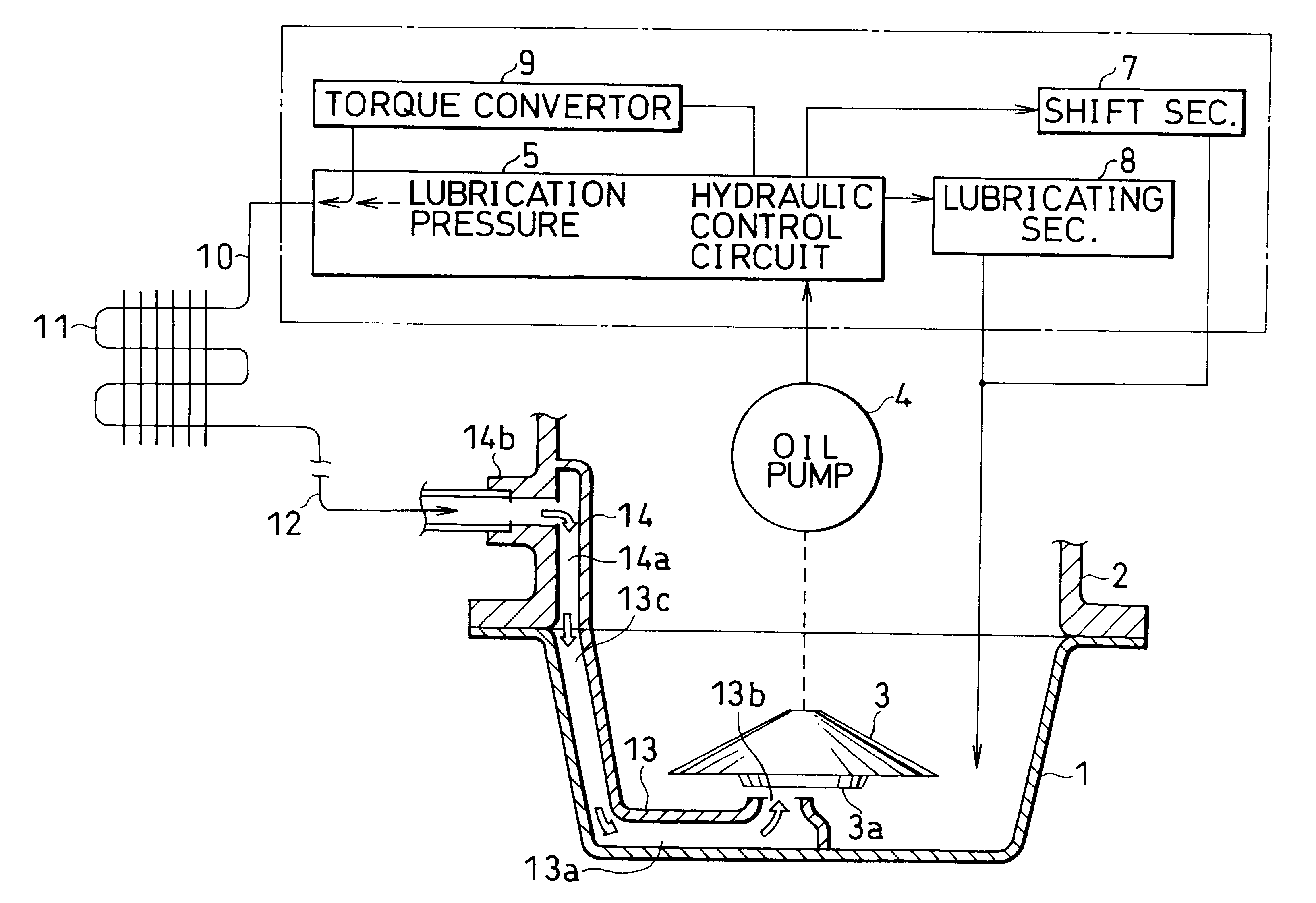
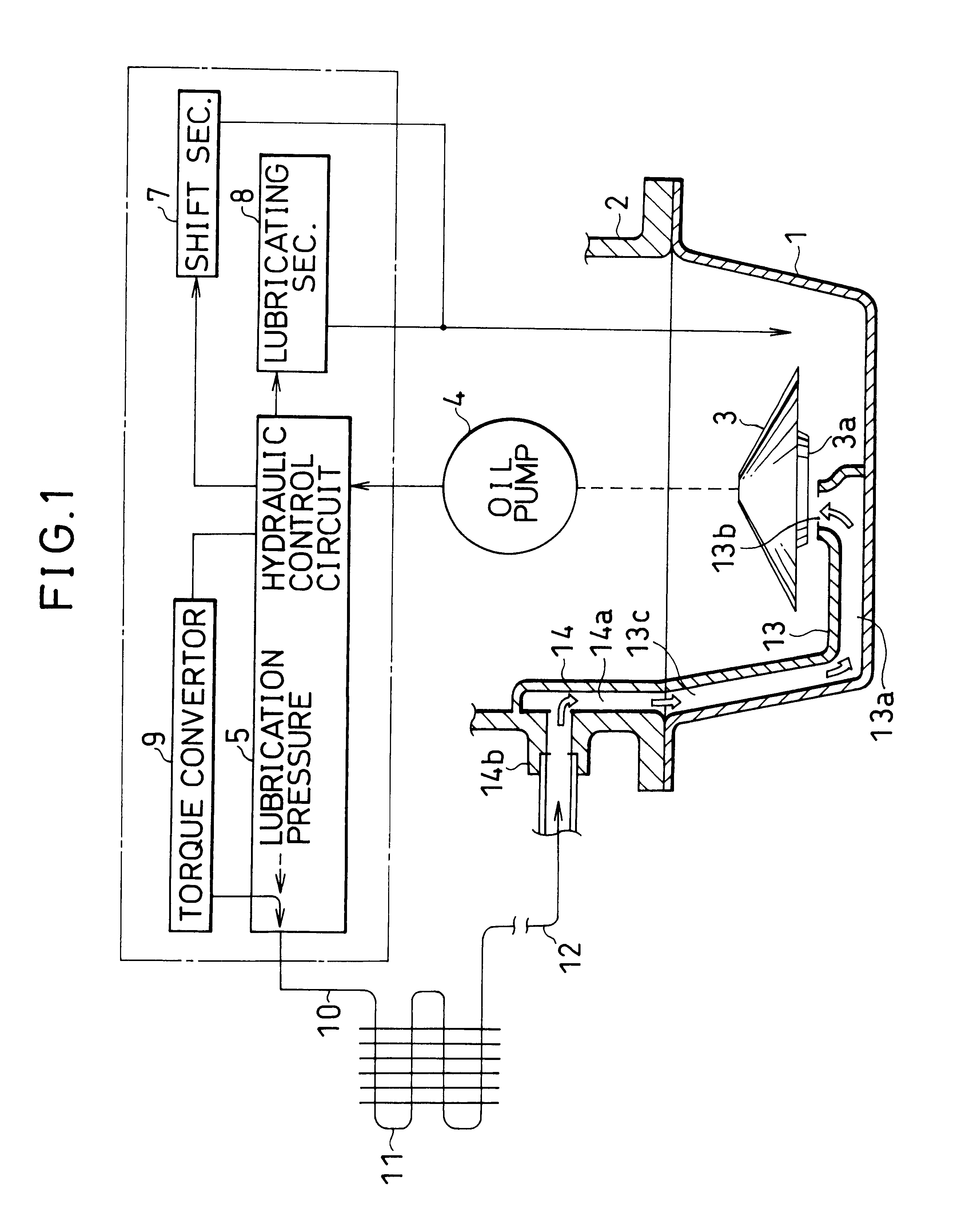
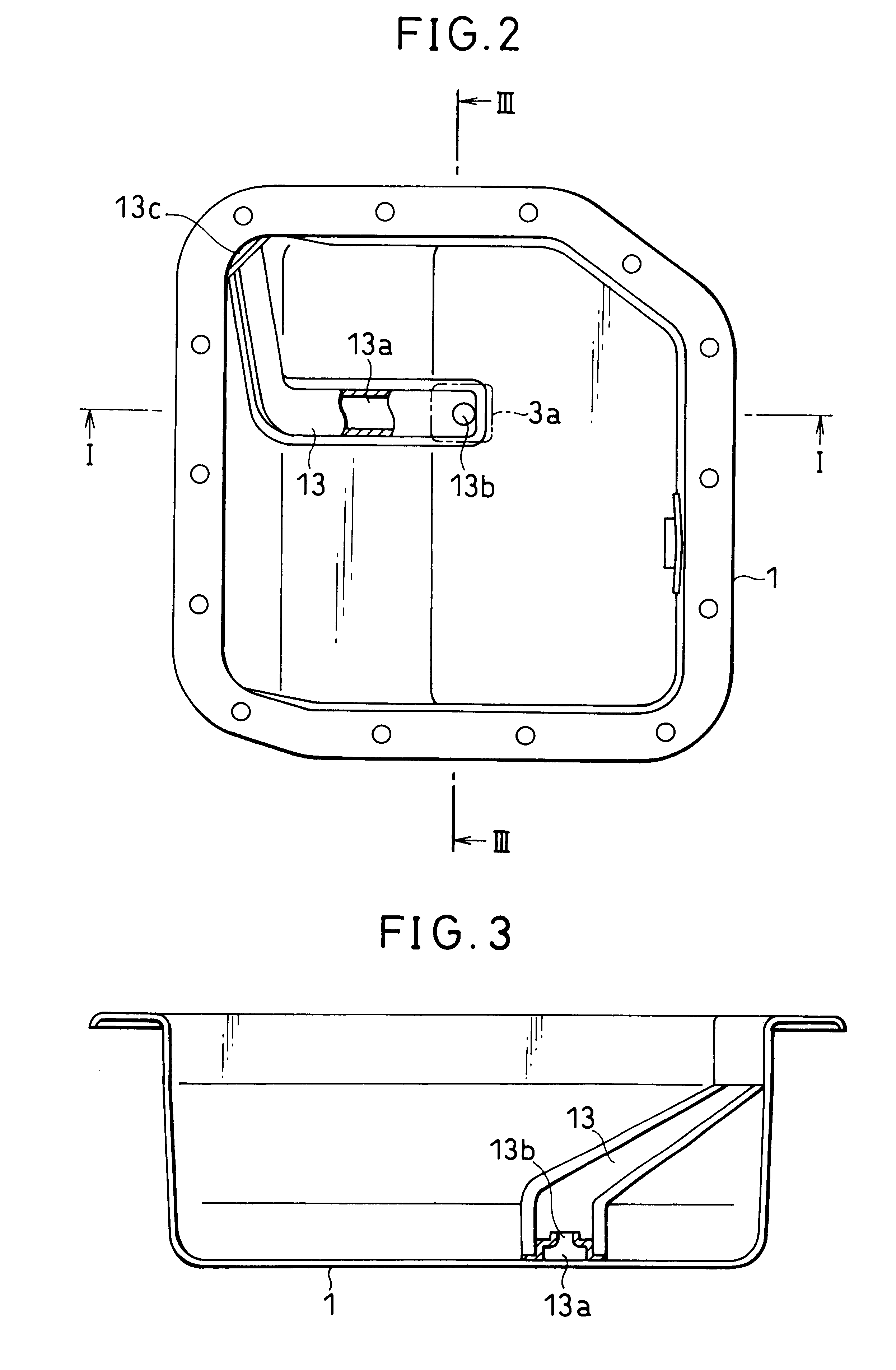
FIGS. 6 through 8 show the present invention. FIG. 6 is a schematic view of a hydraulic circuit of an automatic transmission taken along a line VI--VI of FIG. 8. FIG. 7 is a side view as viewed from the left side of FIG. 8 and FIG. 8 is a top view of an oil pan.

In the first embodiment, the outer pipe 12 connected with the downstream of the oil cooler 11 communicates with the oil passage 13a through the oil passage 14a provided in the transmission case 2, however in this embodiment, the outer pipe 12 is directly connected with the oil pan 1. The feature of the embodiment is a simplification of the construction.

Specifically, there is provided an inlet port 1a on the upper side wall surface of the oil pan 1. Further, the inlet port 1a communicates on the inside thereof 1 with the oil passage 13a formed in the same manner as in the first embodiment.

A union nut 18 is welded on the outside of the inlet port la and a union screw 19 is fastened to the union nut 18 through a T-connector 20 a...


PUM


Abstract

A part of oil sucked by an oil pump is circulated to an oil pan through a hydraulic control circuit, an oil cooler and an oil passage provided in a transmission case and the oil pan. The oil guided to the oil pan is gushed out from a discharge port of the oil passage toward a suction port of an oil strainer communicating with the oil pump. The discharge port of the oil passage is disposed opposite and adjacent to the suction port of the oil strainer so that only the oil containing a small number of bubbles is sucked by the oil pump.

Description

1. Field of the InventionThe present invention relates to an oil circulating apparatus for an automatic transmission and more particularly to an oil circulating apparatus in which air jam noise can be reduced by supplying an oil containing a small number of bubbles to an oil pump.2. Discussion of the Background ArtGenerally, automatic transmission fluid (ATF) for operating and lubricating an automatic transmission including a multi-stage transmission and a continuously variable transmission, is reserved in an oil reservoir such as oil pan and the like provided under the automatic transmission. The automatic transmission fluid reserved in the oil pan is sucked up by an oil pump through an oil strainer and supplied to a torque converter, miscellaneous lubrication parts, a hydraulic servo mechanism and the like, after being regulated to a specified pressure in a hydraulic circuit. The automatic transmission fluid discharged from the servo mechanism and the lubrication parts is returned...

Claims


Application Information

Patent Timeline
IPC IPC(8): F16H57/04F01M11/00
CPCF16H57/0434F16H57/0456F01M5/002F01M11/02F01M2011/0058F01M2011/0066F01M2011/007Y10T74/2186F16H2061/004F16N27/005F16H57/0404
Inventor OGAWA, HIROSHIMURAKAMI, MAMORUNAKAYAMA, JUN
Owner FUJI JUKOGYO KK
Why Eureka
Try Eureka