Bat weight and protector

a bat weight and protector technology, applied in the field of bat weight and protector, can solve the problems of prohibitive placement of the bat weight of the prior art, increased weight, and danger of the prior art devi

Inactive Publication Date: 2003-03-18
OTTS PROD CO
View PDF12 Cites 41 Cited by
  • Summary
  • Abstract
  • Description
  • Claims
  • Application Information

AI Technical Summary

Benefits of technology

A further significant aspect and feature of the present invention is a water resistant device that will not be affected by rain and will not rust.
An additional significant aspect and feature of the present invention is webbing straps which are durable, light and strong.
One object of the present invention is to provide a bat weight which allocates the weight to the barrel end of the bat.
Another object of the present invention is to use less weight to achieve the same resistance during a practice swing.

Problems solved by technology

The location of the bat weight of the prior art is prohibitive and requires more weight to achieve the desired effect to warm up a batter.
Prior art devices are dangerous if accidental detachment occurs during use.
It is very soft and unlikely to cause harm if detachment from the bat occurs.

Method used


Image

  • Bat weight and protector
  • Bat weight and protector
  • Bat weight and protector

Examples


Embodiment Construction

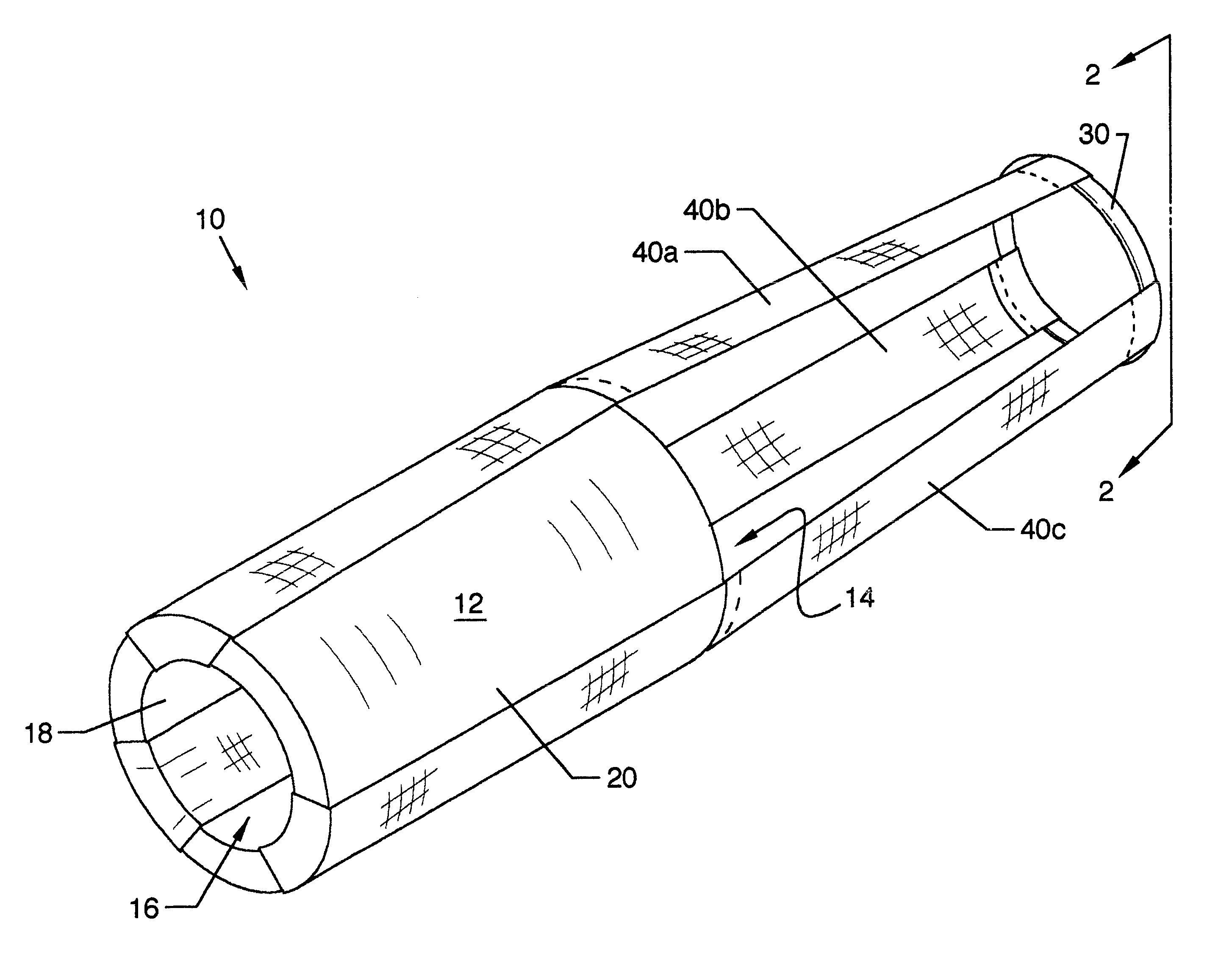
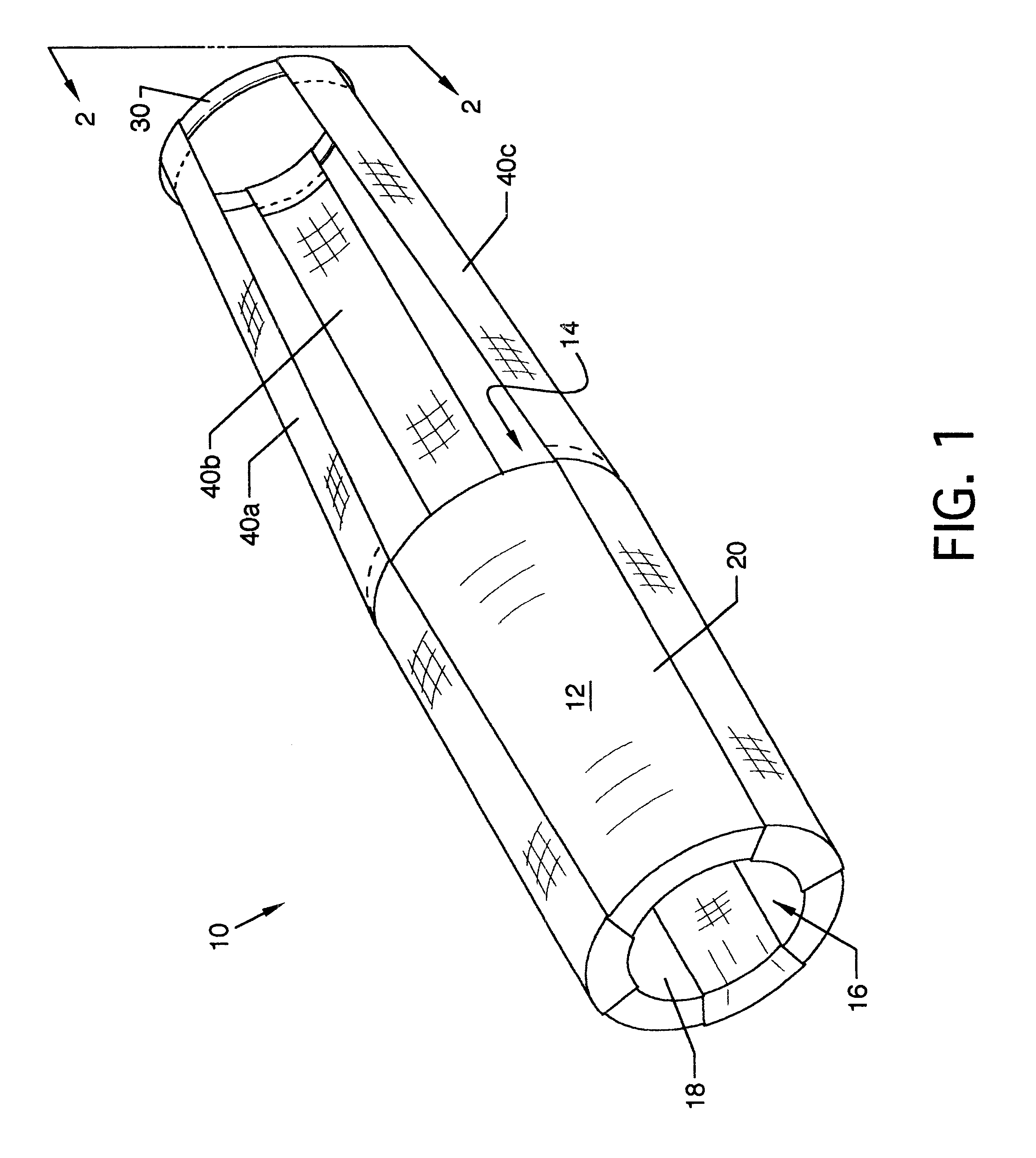
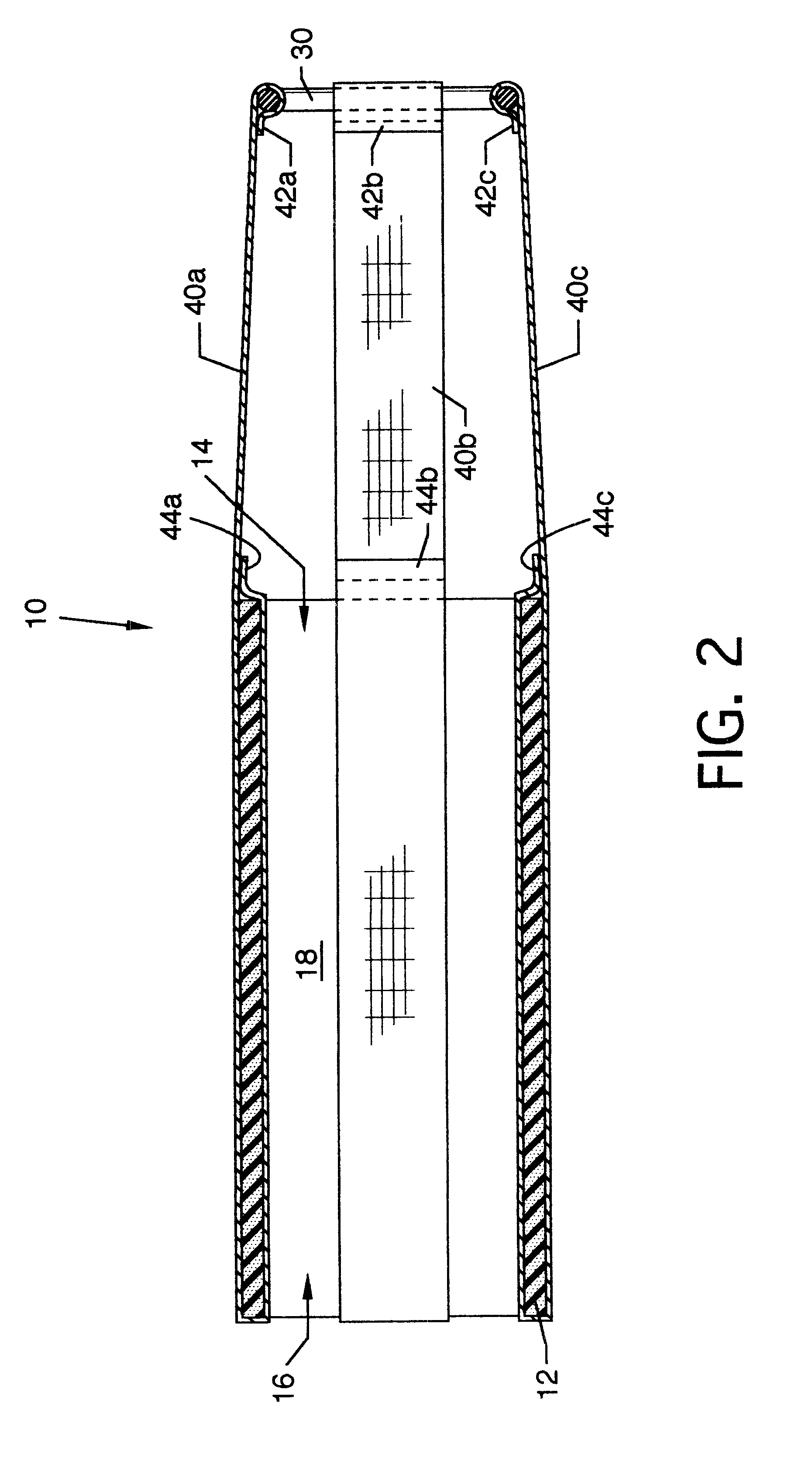
FIG. 3 illustrates a side view of the bat weight and protector 10 appropriately positioned over and about a bat 50, where all numerals mentioned before correspond to those elements previously described. The knob end 56 of bat 50 is slid through the interior of cylindrical portion 12 and through the retainer ring 30. The bat weight and protector 10 is then further slid toward the barrel end 52 of bat 50 until retainer ring 30 is seated against the tapered portion 54 of bat 50. The interior diameter of cylindrical portion 12 is equal to or greater than the exterior diameter of the barrel end 52 of bat 50. The bat weight and protector 10 is frictionally engaged by the bat 50 and is further held in place by centrifugal force when the batter swings bat 50 during warm-ups. Optionally, a clip (not illustrated) may be stitched to any of the webbing straps 40a-40c for clipping the bat weight and protector 10 engaged over and about the bat 50 to a fence when not in use.

Various modifications c...


PUM


Abstract

A bat weight and protector which is a removable soft-sided weight and protector for the attachment to a baseball or softball bat for the purpose of warming up a batter in the on-deck circle, prior to entering the batter's box and facing the pitcher. The bat weight and protector is comprised of a soft weighted cylindrical portion made of rubber or other suitable material, a retainer ring and webbing straps, which at one end are equally spaced around a retainer ring and stitched thereto, and at the opposite end are looped around the cylindrical portion and stitched thereto. A knob end of a bat is passed through the cylindrical portion of the bat weight and protector and further through the retainer ring until the tapered portion of the bat prevents further travel. In this position, the cylindrical portion of the bat weight and protector is over and about a barrel of the bat. This position maximizes the batter's swing resistance during warm-ups and protects the striking surface of the bat.

Description

CROSS REFERENCES TO CO-PENDING APPLICATIONSNone.1. Field of the InventionThe present invention is for a bat weight and protector, and more particularly, pertains to a bat weight and protector for use with a baseball or softball bat. Swing resistant methods and devices have been in existence for many years. A common method for increasing swing resistance is to swing multiple units of the apparatus one would eventually use to strike a ball. For example, a baseball player would swing multiple bats to warm himself up. Two other methods include a separate rigid weighted cylinder that would slide over the bat barrel, but not exceed the tapered end of the bat's barrel, and a weighted donut slid over the knob and rest near the grip of the tapered portion of the bat. The more distal the weight from the barrel end of the bat, the heavier the weight needs to be, and the more proximal the weight to the barrel end of the bat, the less weight required to produce the necessary swing resistance to ...

Claims


Application Information

Patent Timeline
Patent Type & Authority Patents(United States)
IPC IPC(8): A63B59/06A63B59/00A63B69/36
CPCA63B59/06A63B69/3638A63B59/50A63B59/60A63B2102/18
Inventor OTTEN, GREGG G.COSTIGAN, REGINALD P.
Owner OTTS PROD CO
Why Eureka
Try Eureka