Bat with composite handle

a bat and handle technology, applied in the field of ball bats, can solve the problems of reducing affecting the performance of the bat, and reducing the range of motion of the bat, so as to achieve good impact response, effective transfer of power to the batted ball, and good distance

Inactive Publication Date: 2005-09-20
WILSON SPORTING GOODS
View PDF11 Cites 29 Cited by
  • Summary
  • Abstract
  • Description
  • Claims
  • Application Information

AI Technical Summary

Benefits of technology

[0003]Tubular metallic baseball bats are well known in the art. A familiar example is a tubular aluminum bat. Such bats have the advantage of a generally good impact response, meaning that the bat effectively transfers power to a batted ball. This effective power transfer results in ball players achieving good distances with batted balls. An additional advantage is improved durability over crack-prone wooden bats.

Problems solved by technology

An attempt to increase the durability of the bat often produces an adverse effect on the bat's performance, as by possibly increasing its overall weight and stiffness, or having less than optimum weight distribution.
Accordingly, such a design does not allow for maximum energy transfer from the handle to the barrel during hitting.

Method used


Image

  • Bat with composite handle
  • Bat with composite handle
  • Bat with composite handle

Examples


Embodiment Construction

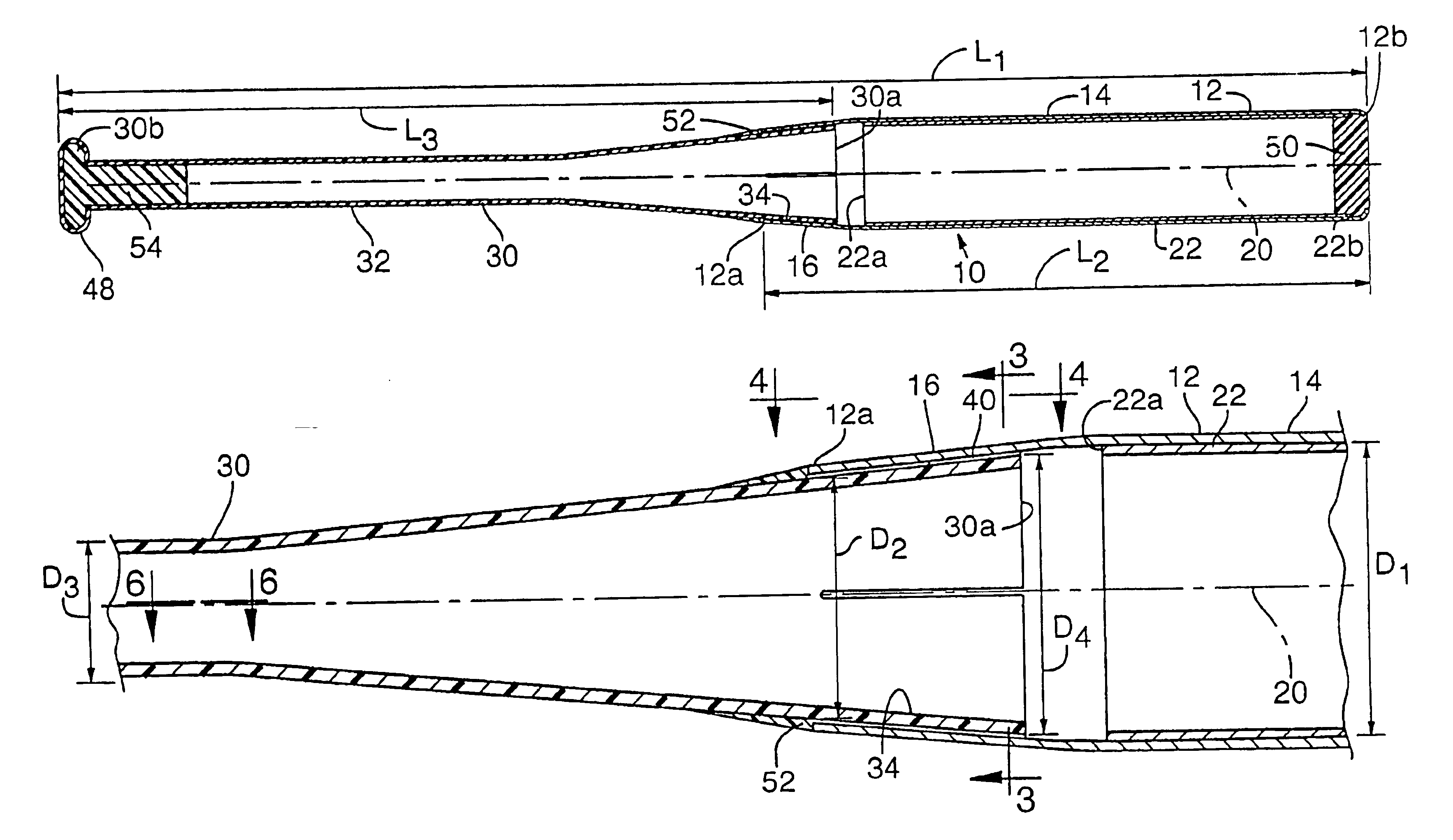
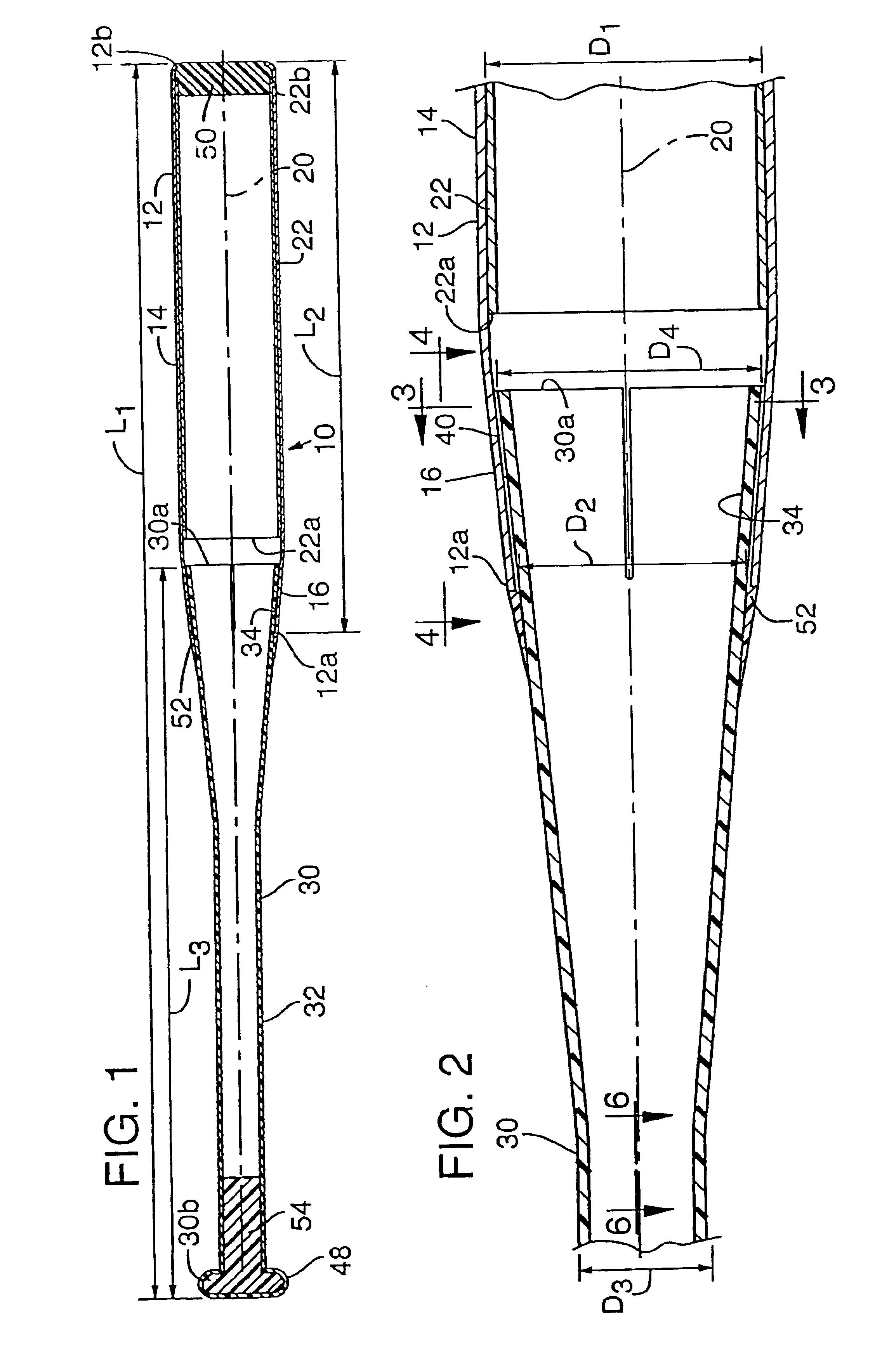
[0028]Referring to FIG. 1, an elongate tubular ball bat 10 having a longitudinal axis, or centerline, 20 comprises an elongate tubular striking member 12. The striking member has a proximal, or inner, end 12a and a distal, or outer, end 12b. A striking region 14 is disposed intermediate ends 12a, 12b. A frusto-conical juncture section 16 of the striking member adjacent end 12a converges toward centerline 20 on progressing toward end 12a.

[0029]In the embodiment illustrated in FIGS. 1 and 2 striking region 14 has a substantially cylindrical inner cavity, with an inner diameter D1. A cylindrical tubular insert 22 is received in the striking region cavity to form a multiple-wall bat. The insert has proximal, or inner, and distal, or outer, ends 22a, 22b, respectively. End 22a is disposed adjacent juncture section 16. The bat also could be made as a single-wall bat without insert 22.

[0030]Juncture section 16 has a major diameter equal to D1 and a minor diameter noted D2 at its end 12a. ...


PUM

PropertyMeasurementUnit
lengthaaaaaaaaaa
thickaaaaaaaaaa
thickaaaaaaaaaa

Abstract

A bat has an elongate tubular striking member of a first material, and an elongate handle member of a second material. The handle may be of composite material laid up in selected layers and orientation to produce selected weight distribution, strength, and stiffness and improved batting capabilities. The striking member and handle member may have juncture sections which are substantially rigidly interconnected through mating configurations.

Description

RELATED U.S. APPLICATION DATA[0001]The present application is a continuation of U.S. patent application Ser. No. 10 / 438,489, entitled “Bat With Composite Handle,” filed on May 15, 2003 now U.S. Pat. No. 6,702,698 by Eggiman et al., which is a division of U.S. patent application Ser. No. 10 / 115,593 filed on Apr. 2, 2002 now U.S. Pat. No. 6,743,127 Eggiman et al.FIELD OF THE INVENTION[0002]This invention relates to a ball bat, and more particularly to a ball bat with a striking barrel member made to provide desired striking capabilities, and a handle member made to provide desired swinging capabilities, and a method for manufacturing such which produces a rigid interconnection between the barrel and handle members.BACKGROUND AND SUMMARY OF THE INVENTION[0003]Tubular metallic baseball bats are well known in the art. A familiar example is a tubular aluminum bat. Such bats have the advantage of a generally good impact response, meaning that the bat effectively transfers power to a batted...

Claims


Application Information

Patent Timeline
Patent Type & Authority Patents(United States)
IPC IPC(8): A63B59/06A63B59/00B29C70/04B29C70/32
CPCA63B59/0092A63B59/06B29C70/32B29L2031/5227A63B2209/023A63B59/50A63B59/51A63B60/00A63B60/08A63B60/42A63B60/54A63B2102/18A63B59/58
Inventor EGGIMAN, MICHAEL D.GUENTHER, DOUGLAS G.FRITZKE, MARK A.
Owner WILSON SPORTING GOODS
Why Eureka
Try Eureka